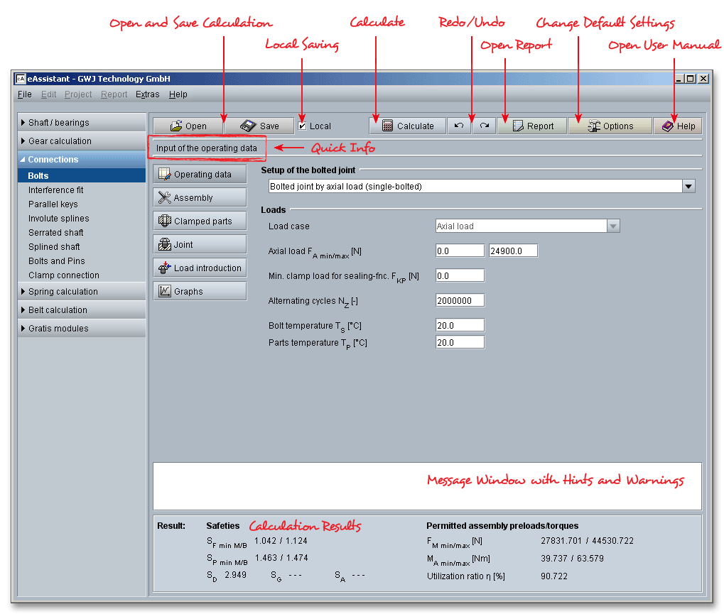
Please login with your userame and your password. To start the calculation module for bolted joints, please click the menu item ‘Connections’ on the left side and then select the ‘Bolts’.

Bolted joints are one of the most common elements in construction and machine design. They consist of bolts,
nuts and joint members. The parts are held together by a threaded bolt or an assembled bolt and nut. It is a
good way to assemble two parts, in a way they can easily be reassembled again. Bolted joints are intended to
transmit motion and power. Proper tools, such as a wrench or a screwdriver, are absolutely essential for the
tightening or loosening of the jointed bolt. Bolts can be also used for clamping, measuring or adjusting (e.g.,
clamping bolts, locking screws, adjusting screws, measuring screws). Bolts, nuts and the threads are
standardized.
VDI 2230 is the basic guideline for the calculation of bolted joints. The stipulations of this guideline apply to steel
bolts (fastening threads with \(60^{\circ }\) flank angle) in highly stressed and high-strength bolted joints for strength grades
8.8 to 12.9 or 70 and 80 and frictional transmission of the working load which in all cases is introduced via the
clamped components. This usually consists of a static or dynamic axial force (that is, the direction of
action is parallel to the bolt axis). In addition, bending moments and transverse forces may be
present. The guideline applies to a limited size of the contact areas at the inner interfaces. If this
limiting value is exceeded, the specified relationships no longer apply or a larger calculation error
occurs.
The material properties based on the tables in VDI 2230 apply only at room temperature, i.e. appropriate
allowance must be made for their temperature dependence at lower and higher temperatures. Extreme stresses
(e.g. corrosion), sudden and stochastic loads are not treated.
Please note: The guideline in principle does not do away with the need for experimental and/or numerical
(FEM, BEM) tests for verifying the calculation results. This is to be recommended, in particular in the case of
critical joints.
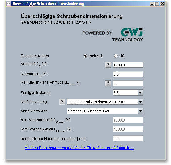
The VDI 2230-1 guideline allows for the estimation of a bolt diameter and strength. The procedure provides a rough estimate of the bolt size as a starting point for more detailed VDI calculations to prevent potential failure modes of the joint. The dimensioning uses a simplified stage model based on loads, loading types and tightening technique. The free calculation module ‘Rough calculation for bolted joints’ can be used to easily determine the minimum bolt diameter.
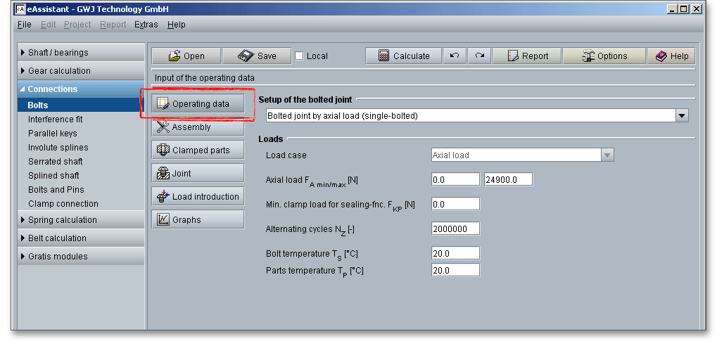
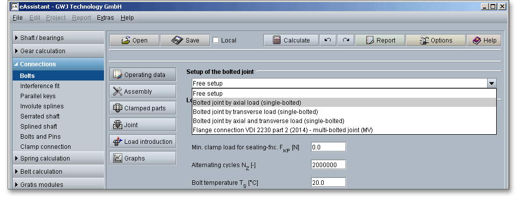
Click the input mask ‘Operating data’ in order to determine the setup of the bolted joint. Single bolted joints
under axial and transverse load as well as flange connections can be selected from the listbox. It is also
possible to define an individual setup. eAssistant calculates bolted joints in accordance with VDI
2230 Part 1 ‘Systematic calculation of highly stressed bolted joints - Joints with one cylindrical
bolt’.
Multi-bolted joints are very complex and it is often difficult to describe load and deformation behaviour mathematically. Standard VDI 2230 Part 1 is recognized as a standard work for calculating high-strength bolted joints. It assumes a knowledge of the relevant loading and geometrical parameters and applies to single-bolt joints. This means that before the actual calculation, which usually concerns several bolts within a contact area, it will be necessary to determine the most highly loaded bolted joint together with its stress levels and separate it out virtually.
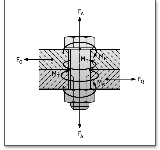
The calculation of a bolted joint is based on the external working load \(F_{B}\) acting on the joint. In operation the joints absorb axially acting working load \(F_{A}\), a transverse load \(F_{Q}\), a bending moment \(M_{B}\) and possibly a torsional moment \(M_{T}\). The initial quantities \(F_{A}\), \(F_{Q}\), \(M_{T}\) and in some cases \(M_{B}\) are subsequently assumed to be known and are the basis for the dimensioning.
Open the listbox and select a configuration. The following configurations can be determined:
Select the option ‘Free setup’ from the listbox to define an individual configuration. Choose a load case and the corresponding input fields appear where you enter your values.
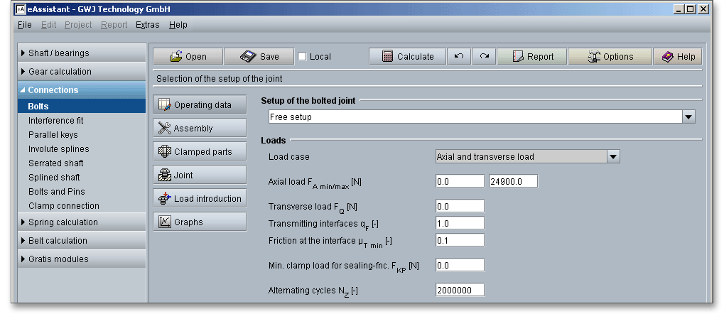
In addition to the working loads, a minimum clamp load \(F_{K}\) is required for pressing the bolted parts together. The
clamp load is needed for sealing functions, friction grip and prevention of one-sided opening at
the interface. The self-loosening leads to the partial loss or complete loss of the clamp load, it
can cause the bolt to loosen. The working loads and the minimum clamp load are assumed to
be known. The requisite clamp load for reaching a sealing effect can be entered into the input
field.
The quantity and direction of the working load can change over time. Therefore, the frequency and the results of
the load changes have to be estimated. Several hundred load cycles during the durability cause no damage
compared to constant static stress.
The maximum number of alternating cycles is \(N_{D} = 2 \times 10^{6}\). According to VDI 2230, a higher number of alternating cycles
does not have a considerable effect on the calculation of the fatigue limit. VDI 2230 recommends \(N_{Z} > 10^{4}\) as the lower
limit.
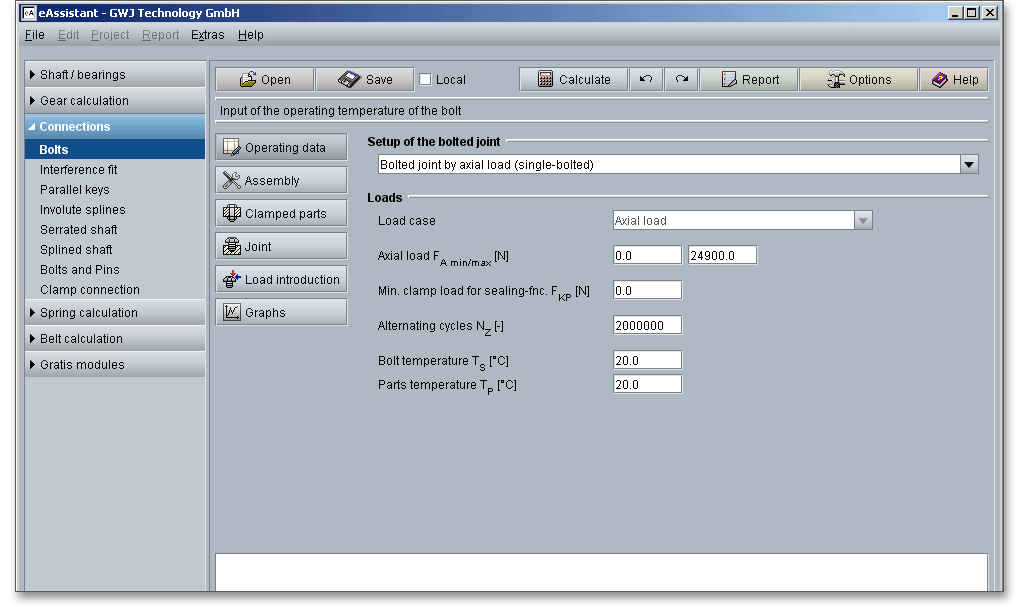
The temperature has a considerable effect on the bolted joint. The impairment is caused by the mechanical and physical properties of the material (modulus of elasticity and thermal expansion coefficient). It is to be taken into account that lower and higher temperatures can change the mechanical and functional properties of the bolt. The modulus of elasticity, the permissible stresses and the thermal expansion coefficient change. Since the material properties are saved for a room temperature of \(20^{\circ }\), the changes must be taken into account. Different temperatures can be defined for the bolt and for the clamped parts. It is to be taken into account that the temperature differences between the bolt and the clamped parts should not be too large. Different thermal expansion coefficients of the bolt and of the clamped parts lead to differential expansions which can lead to a change in the preload. Preload changes involve a temperature-related change of the surface pressure in the head bearing surface which stresses the clamped parts significantly higher. It is very rare that the bolt becomes warmer than the clamped part. In such cases the bolts are provided with a very high preload at room temperature so that there is a sufficient clamping force even during the reduction in preload. Furthermore, a low thermal expansion coefficient should be used for the bolt material.
If a bolt gets tightened, the internal and external threads are pressed together. A frictional resistance is
produced. Pressing the bolt head or the nut to the base causes extra frictional resistance to the bolt. A proper
functioning of the bolted joint substantially depends on the assembly. Therefore, the tightening technique and
the assembly preloads have a considerable effect on the bolted joint.
Bolted joints can be classified depending on the tightening technique: a distinction is made between
non-preloaded joints and preloaded joints. Non-preloaded joints are rarely found in practice, e.g. for extracting or
adjusting devices, preloaded joints are used more often. During the assembly of the joint, an (assembly) preload
is produced. In addition to the preload, a working load is transmitted.
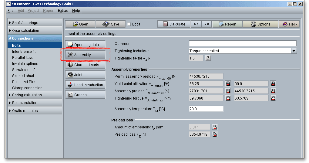
The calculation module offers the generally usual tightening techniques. The tightening factor is set automatically depending on the selected tightening technique. The tightening factor can be individually defined. An individual specification of the utilization of the yield point (e.g., 100% instead of 90%) is also possible.
There are several ways to tighten a bolted joint. Bolts behave differently during the assembly and that is why the clamping forces may vary within wide limits. The tightening technique has a major influence on the scatter of the assembly preload. In order to keep the scatter of the tightening factor as small as possible, a higher level of assembly should be used. Since the tightening technique considerably influences the required size of the bolt, it is necessary to carefully select and carefully use the tightening technique selected for the assembly and based on the calculation. A joint tightened by hand behaves completely differently from one tightened using a power tool. The precision of the different tightening methods vary widely. This means that it is of high importance to choose the right tightening method for the job. Not every tightening technique is appropriate for every bolted joint. Please note, however, that whatever method is used to tighten a bolt, a degree of bolt preload scatter is to be expected. A distinction is to be made between the following tightening techniques:
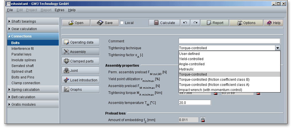
In the yield-controlled tightening technique, the joint is first of all preloaded with a snug torque. Then the torque
and the angle of rotation are measured. An electronic control system is used that is sensitive to the torque
gradient of the bolt being tightened. Rapid detection of the change in slope of this gradient indicates
the yield point has been reached and stops the tightening process so that overstressing is hardly
possible.
When using the angle-controlled tightening process, both torque and angle are used as the controlling factor.
First the joint is loaded - as for yield-controlled tightening - with a snug torque so that the clamped surfaces are
pulled together until all the interfaces are completely closed. Subsequently a defined angle will be applied, which
is measured from the point the snug torque is achieved, with which the bolt will be tightened to or beyond
the yield point. Practice has shown that this technique only reaches its highest precision when
the bolt is tightened into the plastic range, because angle errors then have almost no effect on
account of the approximately horizontal line of the deformation characteristic within the plastic
range. A series of tests is necessary to determine the retightening angle. Because of the bolt being
tightened beyond yield, its re-use is limited. This technique is suitable for individual assemblies and
mass production. It is also used in the automotive industry. In the case of yield and angle-controlled
tightening beyond the elastic limit, the bolts are utilized up to at least 100% of their respective yield
point.
An alternative method of tightening the bolts is by hydraulic tightening. Of the tractive methods, hydraulic
clamping is one in which the assembly preload \(F_{M}\) is generated without friction and thus free of torsion by an axial
lengthening of the bolt effected by hydraulic clamping cylinders. This method uses a small hydraulic ram,
which is placed over the nut and a threaded puller, which is attached to the ram. For this method
to work, the threaded part of the bolt should extend well past the nut. Hydraulic oil from a small
pump applies force on the hydraulic ram, which in turn actuates the puller. As a result, the bolt is
stretched or extended, which allows the nut to be manually rotated. A hydraulic bolt tensioning
tool provides a quick and easy method for tightening large diameter bolts to high and accurate
preloads. This procedure enables the simultaneous tightening of any number of bolts with the same
preload.
Torque-controlled tightening can be carried out with indicating or signalling torque wrenches or motorized bolt
installation spindles. In addition to the controlled variable ‘torque’, the angle of rotation from a threshold torque is
often also measured in order to monitor the tightening operation. This method uses tools that measures the
torque transferred to the fastener and then either gives a signal or turns off when the desired torque is reached.
The torque-controlled tightening process is by far the most commonly used tightening process. This is because
of a relative simple technical process with cost-effective tools and easy handling. The VDI 2230
guideline makes a distinction between the friction coefficient classes A and B which depend on
various factors such as material, surface quality or lubrications. In the case of torque-controlled
tightening beyond the elastic limit, the bolts are utilized up to at least 90% of their respective yield
point.
Impact wrenches transfer energy by means of momentum. An impact wrench delivers quick, repeated impulses
of torque. It is typically powered by air, but it can also be electric. This tightening technique has both advantages
and disadvantages. Impact wrenches are very flexible and simple to use, but the disadvantages are the
comparatively high noise level of the impact wrench and the difficulty in measuring the applied torque
and consequently also the limited possibility to achieve accurate torque control. The tightening
factors are so high that this tightening technique cannot be recommended for highly stressed bolted
joints. The impact wrench is the ideal tool for loosening rusty, stuck, difficult-to-remove nuts and
bolts.
You can individually define the tightening factor. Select ‘User-defined’ from the listbox ‘Tightening technique’.
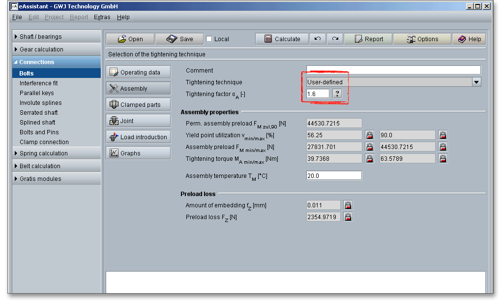
The input field for the tightening factor is enabled and you can enter your own value. If you want to add some own notes, comments or a description, then use the comment line. The comment appears later in the calculation report.
The tightening factor \(\alpha _{A}\) (assembly uncertainty factor) takes into account the scatter of the achievable assembly preload between \(F_{Mmin}\) and \(F_{Mmax}\). It is determined while taking into account the tightening and adjusting techniques. The value of tightening factor used in the design equation depends on the selected tightening method. The tightening factor takes also the lubrication conditions and the surface conditions into account. Based on the tightening technique, the tightening factor is set automatically by the program. But it is also possible to define an individual factor. To do so, select ‘User-defined’ from the listbox. The input field for the tightening factor is renabled and you can add your own value. Guide values for the tightening factor are given in the following table. Click the ‘Question mark’ button to open the table.

| Guide Values for the Tightening Factor \(\alpha _{A}\)1
| ||
| Tightening Factor \(\alpha _{A}\) | Tightening Method | Setting Method |
| 1,2 to 1,4 | Yield-point controlled tightening, | Presetting of the relative- |
| motorized or manual | torque rotation angle coefficient | |
| 1,2 to 1,4 | Rotation-angle controlled | Experimental determination |
| tightening, motorized or manual | of preliminary tightening moment | |
| and rotating angle (stages) | ||
| 1,4 to 1,6 | Torque-controlled tightening | Setting via pressure measurement |
| with hydraulic tool | ||
| 1,4 to 1,6 | Torque-controlled tightening | Experimental determination |
| with torque wrench, signalling | of the setpoint torques | |
| wrench or motorized nut runner | at the original joint member, | |
| with dynamic torque measurement | for example, by elongation | |
| measurement of the bolt | ||
| 1,6 to 2,0 (Coefficient of | Torque-controlled tightening | Determination of the set point |
| friction class B) | with torque wrench, signalling | tightening moment by estimating |
| wrench or motorized nut-runner | the coefficient of friction | |
| 1,7 to 2,5 (Coefficient of | with dynamic torque measurement | (surface and lubrication |
| friction class A) | conditions are a great influence) | |
| 2,5 to 4 | Tightening with impact wrench, | Setting the driver via retightening |
| ‘stalling driver’ or impulse driver, | moment, which is formed from the | |
| tightening by hand | tightening moment (for the estimated | |
| coefficient of friction) plus a | ||
| supplement, manual tightening | ||
| based on subjective assessment | ||
| 1 from: VDI 2230 Part 1, VDI Verlag, Duesseldorf 2015, p. 120, table A8. Guide Values for
the Tightening Factor
| ||
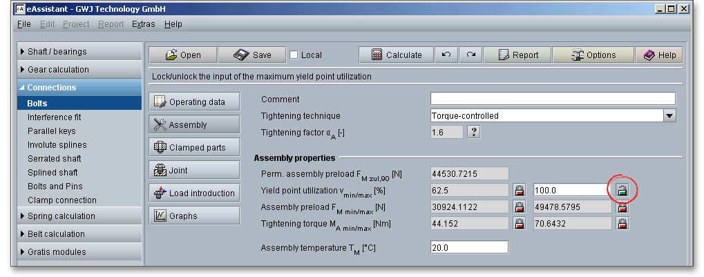
The yield point or the 0.2% yield strength \(R_{p0,2}\) is the material property defined as the stress at which a material begins to deform plastically and it is one of the basic characteristics for the dimensioning of a bolted joint. The yield point indicates the maximum transferable force in newtons (N) per square millimeter of the cross-sectional area for which a permanent deformation of 0.2% remains. The load should not exceed the yield point. If the limit is exceeded, the screw lengthens and eventually fractures and becomes useless due to plastic deformation, the joint will become loose or break. For statically loaded joints, bolts can be preloaded to an initial tension as high as 90% of proof load, retaining 10% as a safety factor. 90% of the minimum yield point is normally taken as a basis for the tightening technique most frequently applied - torque-controlled tightening. In the case of angle and yield-controlled tightening beyond the elastic limit, the bolts are utilized up to at least 100% of their respective yield point. The module gives you the possibility to individually define the utilization of the yield point, for example 100% instead of 90%. Click the ‘Lock’ button to enable the input field and enter your own value.
A proper functioning of the bolted joint essentially depends on the assembly. The assembly preload (also called clamping force) is an important design parameter for bolted joints where safety and reliable performance are dependent on proper initial tension. Conventionally, the design of bolted joints is based to a large extent on preload as the main factor that defines the mechanical behaviour of bolted joints.
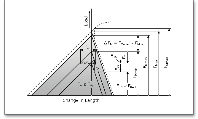
During the assembly of the joint, an (assembly) preload \(F_{M}\) is produced and this produces a clamp load \(F_{K}\) at the
interface. The tightening technique and the assembly preload have a significant effect on the functioning and
durability of the bolted joint. Due to embedding as a result of plastic deformations of the clamped parts, the
assembly preload decreases to the effective preload \(F_{V}\). The assembly preload must be carefully
evaluated.
The assembly preload \(F_{M}\) can be modified by twisting the bolt and nut threads and may be subject to scattering
more or less within wide limits (\(F_{Mmax}\), \(F_{Mmin}\)) depending on the assembly method selected and on the friction conditions. \(F_{Mmax}\) is
the maximum assembly preload for which a bolt must be designed, so that, in spite of lack of precision in the
tightening technique and the expected embedding during operation, the required clamp load in the joint is
produced and maintained. \(F_{Mmin}\) is the required minimum assembly preload. The minimum assembly preload can
occur at \(F_{Mmax}\) as a result of a lack of precision in the tightening technique and maximum friction. The scatters,
which occur during tightening, of the assembly preload \(F_{M}\) between \(F_{Mmin}\) and \(F_{Mmax}\) is summarized in the joint
diagram.
Please note: Click the button ‘Graph’ on the left side to open the joint diagram.
The different working loads, the reduce loss of preload as a result of embedding, the scatter of assembly preload, the type of load introduction as well as the thermal loads are an integral part of the main dimensioning formula, which is the basis for the bolt calculation:
\[F_{Mmin} = F_{Kerf} + (1 - \Phi ) F_{A} + F_{Z} + \Delta F_{Vth}\]
\[F_{Mmax} = \alpha _{A} \cdot F_{Mmin}\]
The assembly preload in the bolted joints is influenced by (VDI 2230, 2015):

Tightening torque is needed to achieve the necessary preload. Since the total tightening torque \(M_{A}\) required
for producing the preload is composed of the thread torque \(M_{G}\) and the head or nut friction moment
\(M_{K}\):
\[M_{A} = M_{G} + M_{K}\]
In addition to purely elastic deformations, local plastic deformations occur in a bolted joint during and after assembly, even during loading below the yield point or limiting surface pressure and these lead to slackening of the joint. Plastic flattening of surface roughness at the bearing areas, the loaded flanks of the mating threads and other interfaces is designated as ‘embedding’. The amount of embedding primarily depends on the type of working load, the number of interfaces and the magnitude of the roughness of the paired surfaces. The higher the number of interfaces, the higher the amount of embedding. The stiffness of the bolted components has a considerable effect on the amount of embedding.
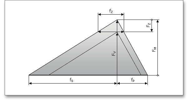
Embedment can mean loss of the assembly preload \(F_{M}\). The assembly preload \(F_{M}\) is reduced to the preload \(F_{V}\) by the loss of preload \(F_{Z}\). Locking elements can compensate the losses of preload. The locking element must ensure that the embedding actions are compensated. Every additional connecting element (e.g. washer or locking rings) increases the amount of embedding. The amounts of embedding which occur in principle in transversely loaded bolted joints are greater than in joints which are only axially loaded. The amount of embedding is automatically determined. There is the possibility to modify the amount of embedding by using the ’Lock’ button.
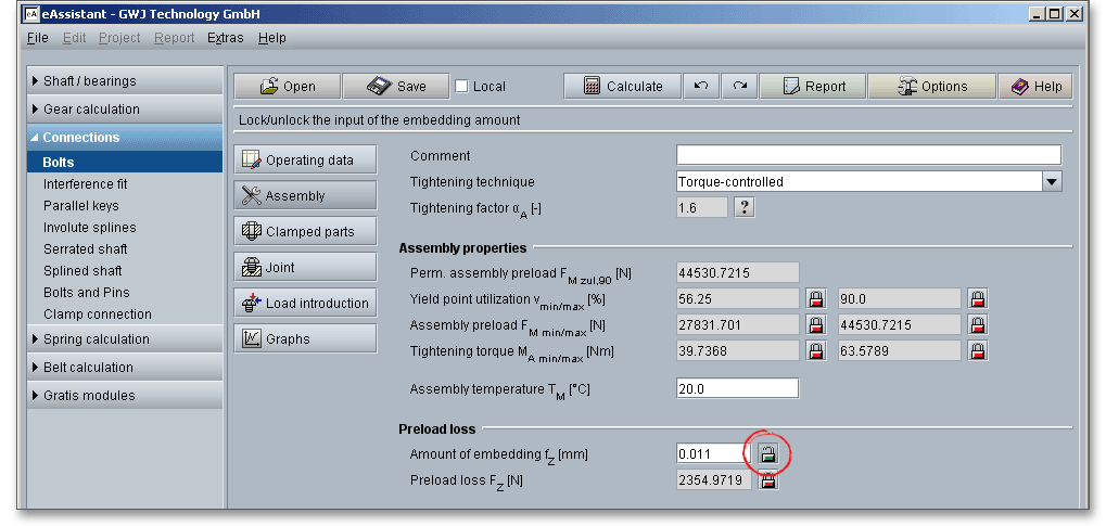
According to VDI 2230, amounts of embedding which already occur during assembly do not lead to a loss of preload. The assembly preload \(F_{M}\) achieved is therefore only reduced by the amount \(F_{Z}\) by the deformations \(f_{Z}\) occurring after assembly has been completed. If the surface roughness is not flattened during the tightening operation (hydraulic or thermal preloading), the amounts of embedding which occur after assembly may be markedly greater than the guide values mentioned here.
VDI 2230 provides some guide values for amounts of embedding of bolts, nuts and compact clamped parts made of steel. According to the guideline, the amounts of embedding which occur in principle in transversely loaded bolted joints are greater than in joints which are only axially loaded.
| Guide Values for Embedment2
| ||||
| Average Roughness | Loading | Guide Values for Embedment in \(\mu m\) | ||
| \(R_{z}\) according to ISO 4287\(^{a)}\) | in the head | per head or | per inner | |
| nut bearing area | interface | |||
| < 10 \(\mu m\) | tension/compression | 3 | 2,5 | 1,5 |
| shear | 3 | 3 | 2 | |
| 10 \(\mu m\) to < 40 \(\mu m\) | tension/compression | 3 | 3 | 2 |
| shear | 3 | 4,5 | 2,5 | |
| 40 \(\mu m\) to < 160 \(\mu m\) | tension/compression | 3 | 4 | 3 |
| shear | 3 | 6,5 | 3,5 | |
| 2 from: VDI 2230 Part 1, VDI Verlag, Duesseldorf 2015, p. 73, table 5. Guide values for
amounts of embedding of bolts, nuts and compact clamped parts made of steel, without
coatings
a) mean value from the maximum surface roughness \(R_{t}\) of at least two sampling lengths; with five sampling lengths \(R_{z}\) corresponds with a good approximation to the ‘old’ \(R_{z}\) of DIN 4768 | ||||
The following design measures compensate or improve the effects of embedding:
Please note: Washers, locking or spring washers under the bold head or nut must not be used for high-strength,
highly preloaded bolts in order to avoid an increase of embedment.
A loss of preload force can occur through the embedding processes during operation. A certain amount of preload is lost due to the flattening of the surface roughness of the material (plates, bolt head and thread). In addition to the assembly preload, the loss of preload must be taken into account. The amount that is lost is not available to tighten the bolted joint. Loss of preload as a result of embedding can be reduced by a small number of interfaces and low surface roughness values. You can influence the loss of preload manually. In the case of highly preloaded bolts with high resilience, the loss of preload due to slackening is slight. In the case of bolts with low resilience, an additional elastic intermediate element (e. g. strain washer) may be necessary in order to avoid an inadmissible loss of preload.
The parts are clamped together by the bolt. When the bolts are tightened, the joint members are tightly pressed together. Subsequent tightening compresses the joint further and the bolt is elongated. The input mask ‘Clamped parts’ defines the geometry of the clamped parts. The clamped parts can be defined as cylinder, prismatic solids or annulus segments. The mask shows, for example, the inputs for the inside or outside diameter of the annulus segment. Furthermore, material, thickness and roughness of the clamped parts can be defined.
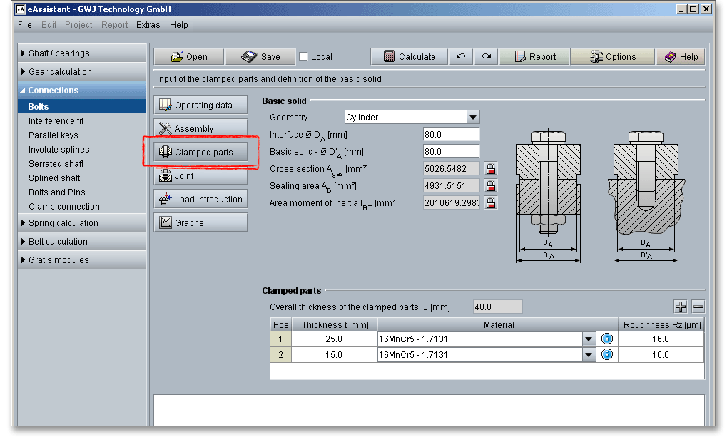
There are several basic types of clamped parts:
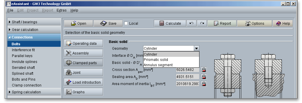
The input parameters that are displayed depend on the selected basic solid geometry. In addition, you get a graphical representation. All resulting values are determined automatically.
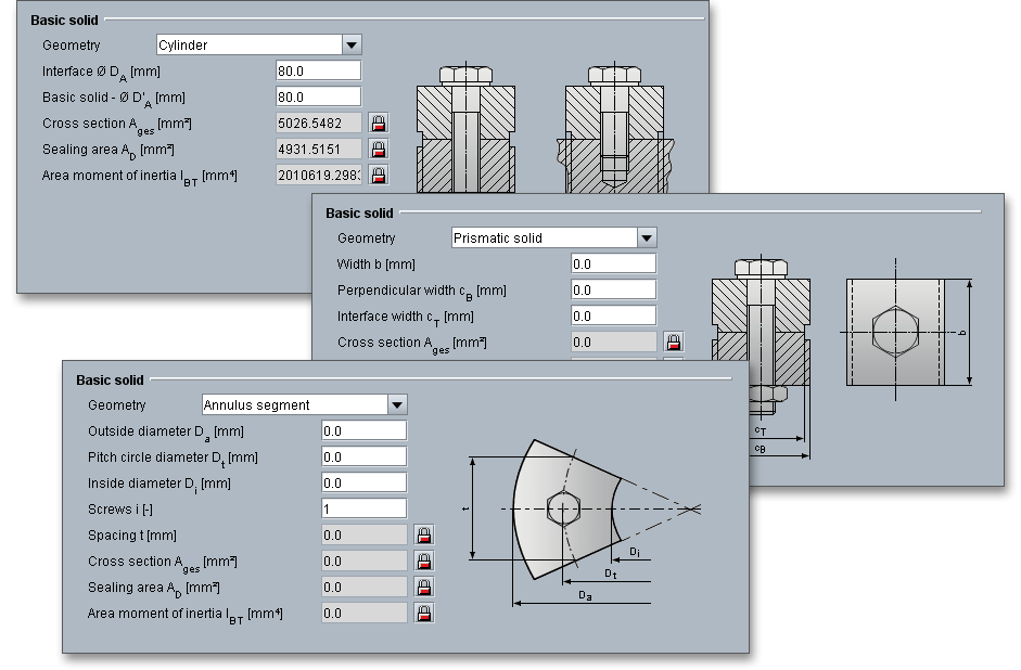
Please note: If you have selected ‘Flange connection VDI 2230 Part 2 (2014) - multi-bolted joint (MV)’ from the
input mask ‘Operating data’, the ‘Annulus segment’ is set automatically as basic geometry. There is at least one
clamped part in single-bolted joints. Multi-bolted joints should have at least two clamped parts. Although there
may be exceptional instances.
The clamped parts can be added to the joint or removed from the joint by means of the table. It is possible to define the thickness, the material as well as the roughness.

A clamped part is added to the joint when you click the ‘+’ button. Click the ‘-’ button to remove the clamped part from the bolted joint. To remove the part from the joint, select the part in the table and click the ‘-’ button. Depending on the bolt length, you can add as many parts to the joint as you want. If the bolt is not long enough, you will get a warning in the message window. To change the bolt length, go to the main mask ‘Joint’. You can select a predefined length from the listbox or click the ‘Lock’ button to enter your own values. The program will indicate to you if the bolt is long enough.

Double-clicking activates the column to modify the value. Material can be defined for each clamped part. Select the appropriate material from the listbox or click the blue circle symbol to open the material database.
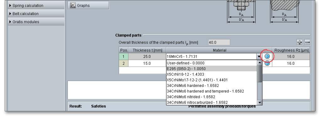
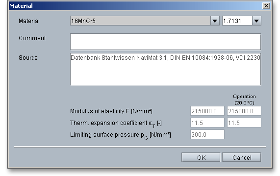
The material database provides some detailed information on the several kinds of material. If the listbox is active, the two arrow keys ‘Up’ and ‘Down’ of your keyboard allows you to search through the database, so you can compare the different values with each other.
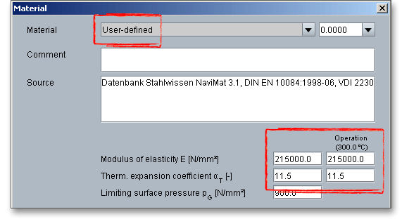
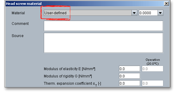
In case there is no material that will fulfill the design requirements, then simply define your individual material. Select the option ‘User-defined’ from the listbox and click the blue circle symbol next to the listbox to open the material database.

The material database opens and and all inputs and options are enabled and you can specify your individual material very easily. Your inputs will be saved to the calculation file.
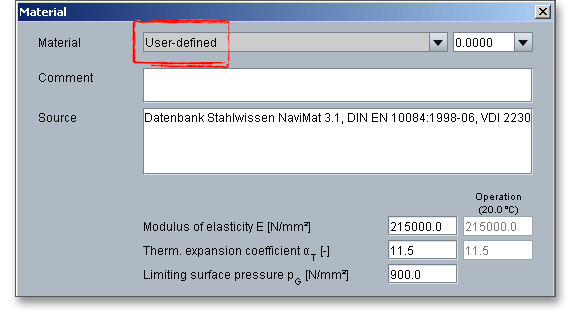
Please note: Please be advised that changing the material will delete your defined inputs and you have to enter
the inputs again.
Since the material properties, such as modulus of elasticity and thermal expansion coefficient, are saved for a room temperature of \(20^{\circ }\), you need to manually adjust the material properties for very high and very low temperatures. Select the entry ‘User-defined’ from the listbox. The input fields for the modulus of elasticity, the thermal expansion coefficient and the limiting surface pressure are enabled and can be modified.
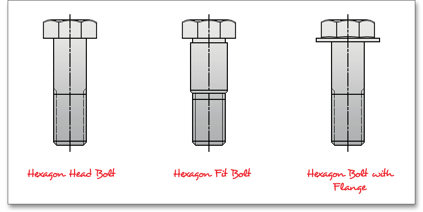
A fixing screw consists of:
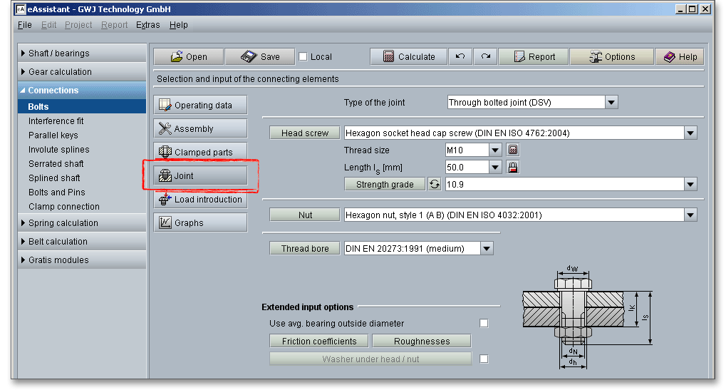
The input mask ‘Joint’ allows to define the properties of the bolt, nut and thread bore. Extended input options include roughness and friction coefficients. You can also add washers under the bolt head or nut.
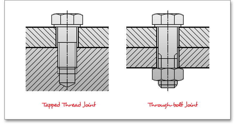
There are two joint types: Tapped thread joints and through-bolt joints. Both are the commonly used assemblies. The types can be selected from the listbox. Depending on the selected joint type, a graphical representation and input options are available. The through-bolt joint and the tapped thread bolt are abbreviated to DSV and ESV in VDI 2230, respectively.

There is a basic difference between tap bolt and through-bolt. The tap bolt is turned into a threaded (tapped) hole in one of the parts being connected and not into a nut. On the other hand, the through-bolt is turned into the nut. The bolt passes through the members to be joined and is secured by tightening the threaded portion of the bolt into the nut. In case of the through-bolts, there are no threads in any parts being fastened. Preloaded through-bolt joints are used to transfer transverse forces via frictional grip, for example, high-strength bolts in structural steelwork.
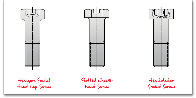
Bolts are standardised and a wide variety is available for different operating conditions and applications. Bolts may be classified according to the form of their heads. There are a lot of different bolt head types. The bolt is preloaded by the application of a torque to the bolt head. There are bolts with hexagon, square and countersunk heads. Simple hexagon-head bolts are often used (as cap screw or stud screw). The square-head bolt is used recessed into a squared hole. It is thus prevented by the walls of the recess from turning during the process of having its nut screwed on. The countersunk-head bolt is used, when it is desirable to sink the bolt head in the surface of the work piece. For reasons of labour safety, bolts that have to secure rotating or moving machine parts are usually countersunk. Applications in structural engineering require high-strength bolted joints. Bolts, nuts and the threads are standardized. The choice of the bolt head will depend upon a number of factors, including size, required strength and tightening technique. The following figure shows a selection of the most common bolt types. Please see the corresponding standard for further information.
Hexagon head bolts: The hexagon head bolt and hexagon nuts are the most common bolts in general
mechanical engineering. The hexagon shaped head permits higher tightening and releasing torques, the
spanner is very easy to adjust, space is required for turning the spanner.
Hexagon socket head cap screw: A hexagon socket head cap screws need less space and and require no
additional wrench space. The bolts have a hexagonal socket in the head and can only be loosened and
tightened with an allen wrench.
Slotted cheese-head screw: Due to their small dimensions they are very easy to install.
High-strength bolted joints: High-strength bolted joints are used widely in the construction of many steel
structures. The preload is higher for high-strength bolted joints than for normal bolted joints. High-strength bolts
have the highest load-bearing capacity. The common strength grades are 8.8, 9.8, 10.9 as well as
12.9.
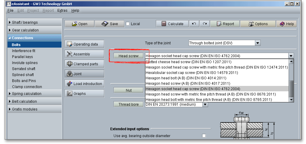
Select the bolt standard directly from the listbox and click the button ‘Head screw’. Clicking the button leads you to the database including all the head screw properties. The suitable bolt diameter and the bolt length are displayed.
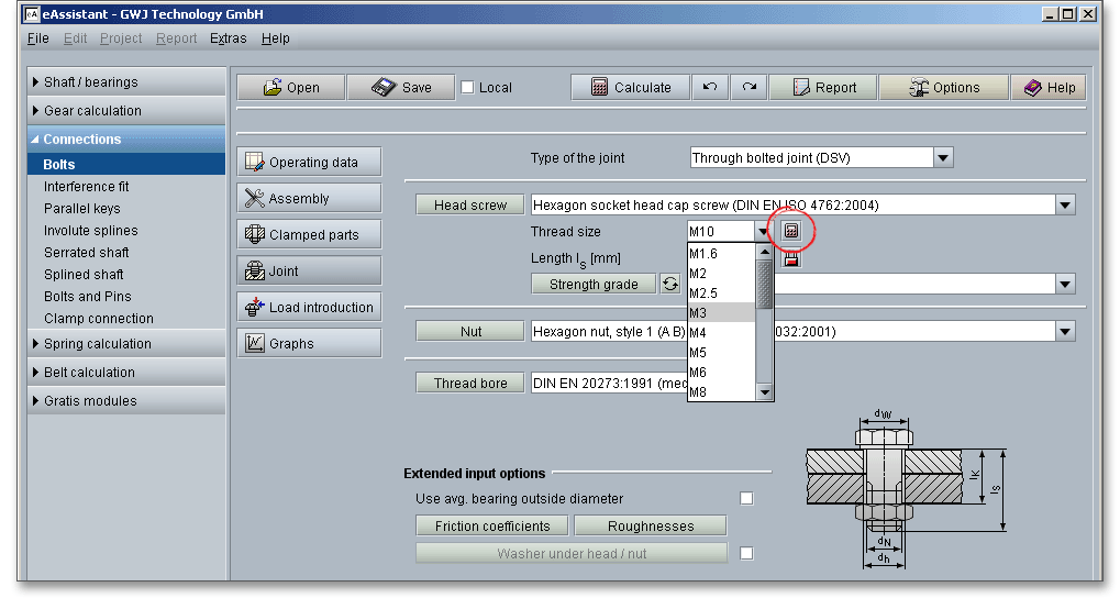
Select the bolt diameter from the listbox. To optimize the bolt diameter, click the ‘Calculator’ symbol next to the listbox and the program recommends you a bolt diameter. The determination of the value is carried out so that the given minimum safety is always fulfilled.
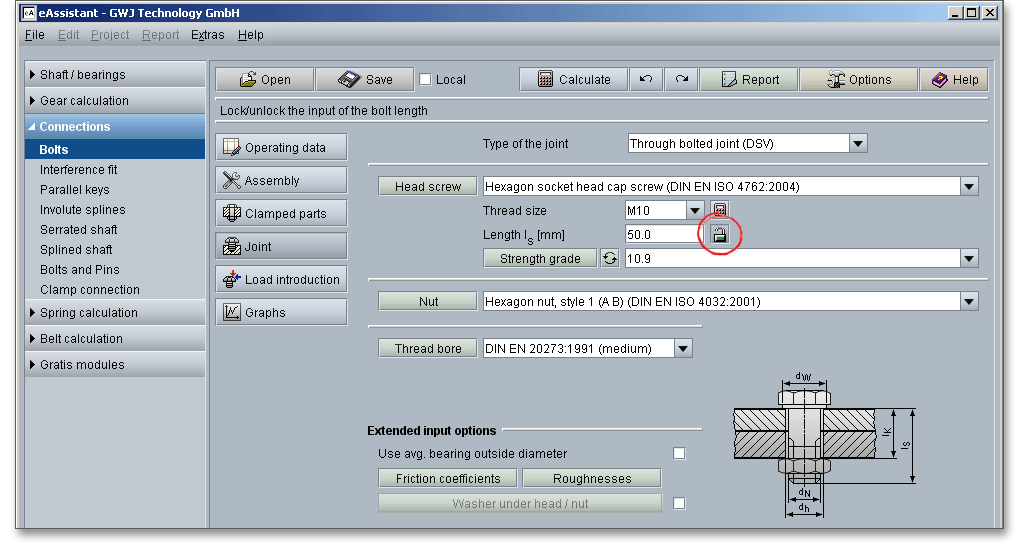
The bolt length can also be selected or manually set. Click the ‘Lock’ button to enable the input field and enter your own value. Click the ‘Lock’ button and the input field is disabled again. The bolt length is set to the next standard length.
Click the button ‘Head screw’ to open the bolt database. By clicking the button you will get detailed information on the selected bolt, for example the bolt head geometry, thread or shank. The table on the left side provides the currently selected bolt length (highlighted in grey) as well as the thread size (bolt diameter). You can select a different length directly from the table. All values, such as bolt head geometry and thread, automatically adjust to the modified bolt length. The listbox ‘Standard’ also allows you to quickly select a new bolt. Click the button ‘OK’ to confirm your selection.
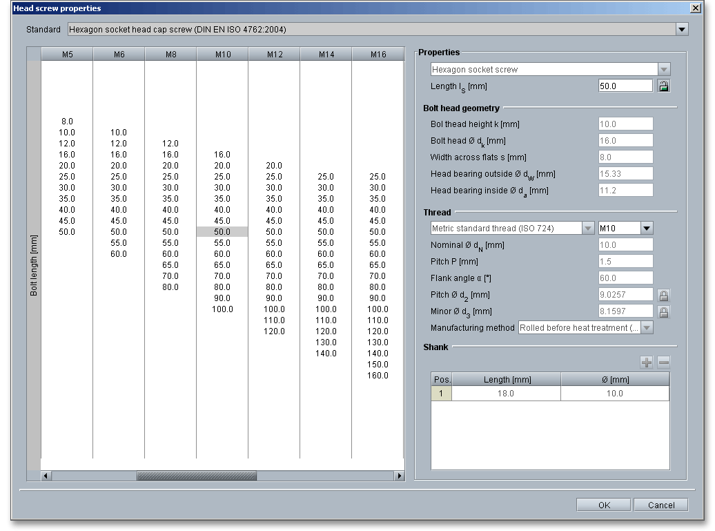
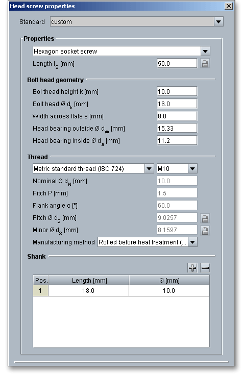
The program allows you to define your own bolt geometry. Select either the entry ‘custom’ from the listbox or click the button ‘Head screw’ to open the database. Click the listbox ‘Standard’ and select ‘custom’.

If you select the entry ‘custom’ all input fields are activated and you can enter the values for your bolt geometry. Your inputs will be saved to the calculation file. Please be advised that changing the bolt will delete your defined inputs and you have to enter the inputs again.
The strength grades (or property class as it is known in the standards) provide information on the mechanical properties, such as the tensile or yield point. Bolts and nuts are classified according to their properties in 10 property classes.

The strength grade consists of two numbers separated by a point, e.g., 4.6, 8.8 or 10.9. The first number corresponds to 1/100 of the nominal tensile strength in \(N/mm^2\). The second figure, multiplied by 10, states the ratio between the lower yield stress and the nominal tensile strength (yield stress ratio) as a percentage. The multiplication of these two figures will give 1/10 of the yield stress in \(N/mm^2\).
Tensile strength \(R_{m}\): The first figure indicates: 1/100 of the minimum tensile strength of the material:
\(R_{m}/100\)
Yield point \(R_{e}\): Both values are multiplied and multiplied again by 10
Tensile strength \(R_{m}\): \(R_{m}\) = 8 x 100 \(N/mm^2\) = 800 \(N/mm^2\)
Yield point \(R_{e}\): \(R_{e}\) = 8 x 8 x 10 \(N/mm^2\) = 640 \(N/mm^2\)
Tensile strength \(R_{m}\): \(R_{m}\) = 10 x 100 \(N/mm^2\) = 1000 \(N/mm^2\)
Yield point \(R_{e}\): \(R_{e}\) = 10 x 9 x 10 \(N/mm^2\) = 900 \(N/m^2\)
The strength grades 4.6, 5.6, 5.8, 6.8, 8.8, 10.9 and 12.9 are quiet common. The standard strength
grade for many industries is 8.8. Apart from flange joints, the strength grades 4.6, 5.6 and 5.8 are
not used very often. The strength grades 10.9 and 12.9 are used for determined and preloaded
bolted joints. If a bolt has strength class 8.8, a nut with a strength class 8 has to be chosen as
well.
Please note: The selection of an appropriate strength grade depends on different factors, for example the size
of loads to be transmitted. If there are no requirements, the 8.8 strength grade can be used for
quenched and tempered bolts. A strength grade below 8.8 can be used where no great strength is
required.
Select the strength grade from the listbox. If you need additional information on the strength grade, then click the button ‘Strength grade’. The dialog window provides, for example, the modulus of elasticity, tensile strength or shearing strength.
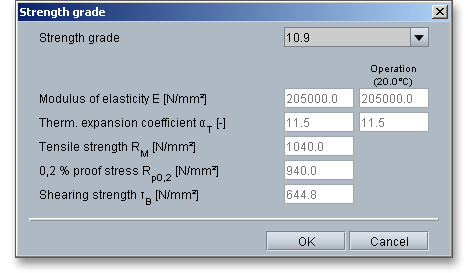
The strength grade can be set manually. Select ‘custom’ from the listbox and add a value for the modulus of elasticity or the shearing strength. The user-defined input will be saved to the calculation file. Please be advised that changing the strength grade will delete your defined inputs and you have to enter the inputs again.
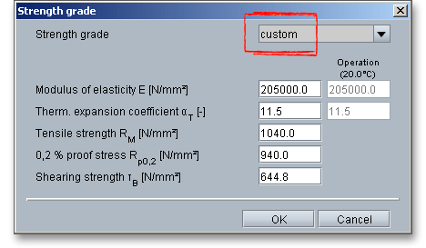
Click the ‘Arrow’ to toggle between the stength grade and the material. Bolted joints can be made from many materials, but most are made from steel. Steel of high to medium strength is the most commonly used material for bolts and nuts. It is important to have a high ductility and good cold forming properties.

Select an appropriate material directly from the listbox or click the button ‘Material’ to open the material database.
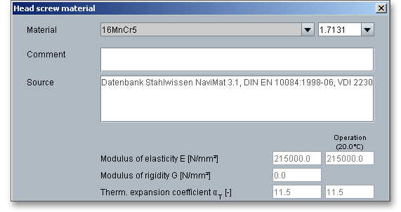
In case there is no material that will fulfill the design requirements, then simply define your individual material. Select the option ‘User-defined’ from the listbox and all inputs and options are enabled and you can specify your individual material very easily. Confirm your entries with ‘OK’. Your inputs will be saved to the calculation file. Please be advised that changing the material will delete your defined inputs and you have to enter the inputs again.
The external thread (bolt) engages the internal thread (nut). The nut is an important part of the bolt assembly and is almost always used opposite a mating bolt to fasten parts together. The nut is a type of fastener with a threaded hole. Nut are used for a through-bolt joints. In this case, the bolt passes through the members to be joined and is secured by tightening the threaded portion of the bolt in a nut. Nuts are tightened from the outside and are either hexagonal or square.
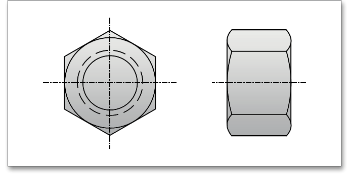
Hexagonal nuts are the most commonly used type of nuts. The nut is tightened with a wrench. Nuts can be classified in three groups: nuts of group A are capable of bearing full load (e.g., DIN EN ISO 4032), nuts of group B with a limited load-bearing capacity (e.g., DIN EN ISO 4035) as well as group C for nuts without a determined load capacity (e.g., DIN 936).
The strength classes of nuts are designated by only one number to indicate the maximum appropriate property class of bolts with which they may be mated. Thus, nut property class is the same as the first number of the bolt designation. The number indicates 1/100 of the minimum tensile strength in newtons per square millimeter (\(N/mm^{2}\)). Marking of hexagonal nuts with the manufacturer’s mark and the strength class is prescribed for all strength classes and with a thread diameter \(\geq M5\), preferably on top of the head. A bolt of a particular property class should be assembled with the equivalent or higher property class of nut to ensure that thread stripping does not occur.
Tensile strength \(R_{m}\): \(R_{m}\) = 8 x 100 \(N/mm^2\) = 800 \(N/mm^2\)
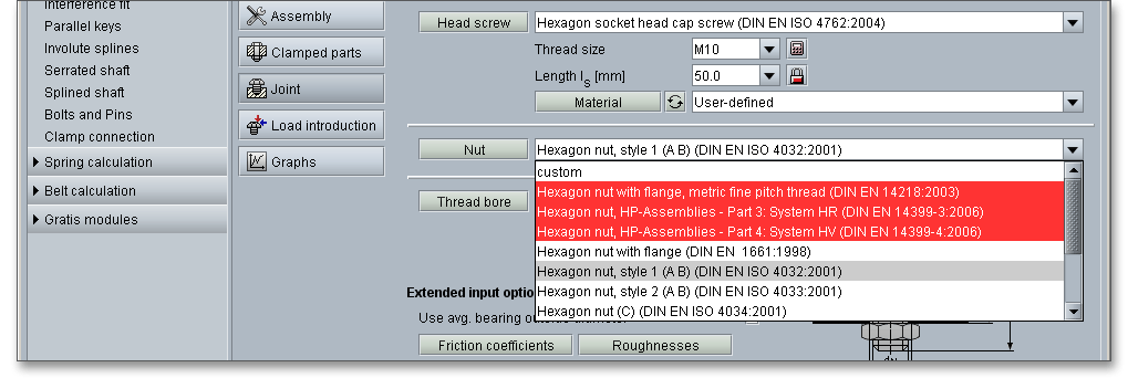
The nut can be selected from the listbox. Nuts that are not suitable for the required application are highlighted in red.
The shape of the nut depends on the application: wing nuts or knurled nuts for tightening by hand, hexagonal,
square, cap or castle nuts can be tightened by using a wrench. Slotted nuts that have grooved heads on
top or round nuts with two holes are used where the space is limited and the joint is not easily
accessible.
Please note: When selecting a nut the general rule is that the grade of the nut should always match the grade
of the bolt or be one grade higher to avoid breaking and thread stripping. Bolted joints with standardized nuts
are capable of bearing full load if the nut strength grade matches the strength grade of the bolt, for example nut
10 with bolt 10.9.
Click the button ‘Nut’ to open a new window that will display additional information on the nut.
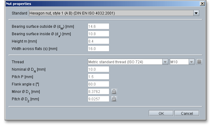
You can define a nut according to your individual requirements. Select the entry ‘custom’ from the listbox and
add your values. If this option is enabled, the thread can be modified accordingly. Select ‘custom’ to modify the
thread. Please be advised that changing the nut will delete your defined inputs and you have to enter the inputs
again.
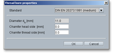
This option gives you the opportunity to define a thread bore. The thread bore standard can be taken from the listbox: DIN EN 20273 fine, medium or rough.

Click the button ‘Thread bore’ to open the thread bore properties. Chamfers at the head side or thread side can be taken into consideration. The VDI 2230 guideline says that in the case of steel, chamfers at the hole can deliver values up to 25% higher (supportive effect).
Very small external dimensions of clamped components result in a reduction in the boundary surface pressure which in some cases is considerable. If washers are used to reduce the surface pressure, care must be taken to ensure that they have sufficient strength and thickness.
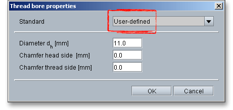
Select the entry ‘User-defined’ from the listbox and enter your own value for the hole diameter \(d_{h}\).
The following table provides dimensions for through holes according to DIN EN 20273.
| ø Dimensions for Through Holes According to DIN EN 202733
| |||
| Thread | Through hole according to DIN EN 20273 | ||
|
| fine | medium | rough |
| M3 | 3,2 | 3,4 | 3,6 |
| M4 | 4,3 | 4,5 | 4,8 |
| M5 | 5,3 | 5,5 | 5,8 |
| M6 | 6,4 | 6,6 | 7 |
| M8 | 8,4 | 9 | 10 |
| M10 | 10,5 | 11 | 12 |
| M12 | 13 | 13,5 | 14,5 |
| M14 | 15 | 15,5 | 16,5 |
| M16 | 17 | 17,5 | 18,5 |
| M20 | 21 | 22 | 24 |
| M24 | 25 | 26 | 28 |
| M30 | 31 | 33 | 35 |
| M36 | 37 | 39 | 42 |
| 3 from: Niemann G., Winter H.: Maschinenelemente, Part 1, Konstruktion und Berechnung
von Verbindungen, Lagern, Wellen, 3rd Edition 2001, Springer-Verlag, p. 441, figure 10.49.
| |||
The magnitude of the friction is expressed by the coefficient of friction in the head bearing area \(\mu _{K}\) and the
coefficient of friction in the thread \(\mu _{G}\). For a typical friction coefficient of \(\mu _{G} \approx 0,14\) the achieved preload falls by 10%, so that
only 80% of the minimum load remains at the yield point. The friction coefficient depend to a great extend on the
surface condition (corroded, sand-blasted, flame-annealed).
If the friction coefficients in the bearing surface of the head or the nut \(\mu _{K}\) or the thread \(\mu _{G}\) are not known, the following table can be consulted in order to establish them.
| Friction Coefficient Classes with Guide Values for Different Materials/Surfaces and
Lubrication States in Bolted Joints4
| |||
| Friction coefficient | Range for | Selection of typical examples for | |
| class | \(\mu _{G}\) und \(\mu _{K}\) | Material/surfaces | Lubricants |
| A | 0,04 to 0,10 | Metallically bright; black oxide; phosphated; galvanic coatings such as Zn, Zn/Fe, Zn/Ni; Zinc laminated coatings | Solid lubricants, such as \(MoS_{2}\), graphite, PTFE, PA, PE, PI in lubricating varnishes, as top coats or in pastes; liquified wax; wax dispersions |
| B | 0,08 to 0,16 | Metalically bright; black oxide; phosphated; galvanic coatings such as Zn, Zn/Fe, Zn/Ni; Zinc laminated coatings; Al and Mg alloys | Solid lubricants, such as \(MoS_{2}\), graphite, PTFE, PA, PE, PI in lubricating varnishes, as top coates or in pastes; liquefied wax; wax dispersions, greases; oils; delivery state |
| Hot-galvanized | \(MoS_{2}\); graphite; wax dispersions |
||
| Organic coatings | with integrated solid lubricant or wax dispersion |
||
| Austenitic steel | Solid lubricants or waxes; pastes |
||
| C | 0,14 to 0,24 | Austenitic steel | Was dispersions; pastes |
| Metallically bright; phosphated | Delivery state (lightly oiled) |
||
| Galvanic coatings such as Zn, Zn/Fe, Zn/Ni; Zinc laminated coatings; adhesive | None |
||
| D | 0,20 to 0,35 | Austenitic steel | Oil |
| Galvanic coatings such as Zn, Zn/Fe; hot-galvanized | None |
||
| E | \(\ge \) 0,30 | Galvanic coatings such as Zn/Fe, Zn/Ni; austenitic steel; Al, Mg alloys | None |
| 4 from: VDI 2230 Part 1, VDI Verlag, Duesseldorf 2015, p. 113, table A5. Friction coefficient
classes with guide values for different materials/surfaces and lubrication states in bolted
joints
| |||
The aim is to achieve coefficients of friction which fit into the friction coefficient class B in order to apply as high a preload as possible with low scatter. This does not automatically mean using the smallest values and that the friction coefficient scatter present corresponds to the class spread. The table applies for room temperature.

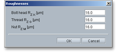
When tightening a bolt, the surface roughnesses are pressed together and deformations occur which leads to embedding. The deformation reduces the surface roughness. The right surface roughness is to be established by the engineer/user. It is to be taken into account that the manufacturing costs for very fine surfaces can be high and rough surfaces cannot perform its intended function. Choosing the right surface roughness depends largely on many factors, for example the function of the bolted joint that needs to be fulfilled or the manufacturing process. The surface roughness has a considerable effect on the amount of embedding and the loss of preload.
A washer is a thin plate typically disk-shaped with a hole that is normally used to provide a seating for nuts and
bolts in order to distribute the load over an area greater than that provided by the bolt head or nut. Washers are
placed under the heads of bolts or under nuts. It also prevents the nut from damaging the metal surface under
the joint. Washers can also seal, cover up oversize holes and act as a spring take up between fastener and
workpiece. They also have the special task of preventing unwanted embedment. If washers are used for
reducing the surface pressure, care is to be taken to ensure that they have sufficient strength and
thickness.
Place a check mark in the box to enable this option. Click the button ‘Washer under head/nut’ to open the dialog.

Since bolt holes could have sharp edges or burrs, washers are used to protect the fillet under the bolt head from
scratching since this is a critical area that is prone to failure. Washers are ideal for oversized or enlongated
holes. If the bolt’s through-hole is oversized, a washer can help prevent pulling the bolt’s head through the hole.
Washers are recommended for use with rough and unmachined surfaces or lower part strength.
Not all screws need washers. In many cases, washers are counterproductive. Washers should
not be used for smooth and hard surfaces. Standard washers may deflect under heavy loading,
so hardened and heavy duty washers are recommended. Washers are available in wide variety
shapes, sizes and materials. Plain washers according to DIN EN ISO 7089 or 7090 (plain chamfered
washers) are used for hexagon head bolt and nuts (product grade A and B) and case-hardened
bolts.
Please activate ‘Under bolt head’ or ‘Under nut’ to place the washer under the bolt head or the nut. The listbox is enabled and you can choose a washer.
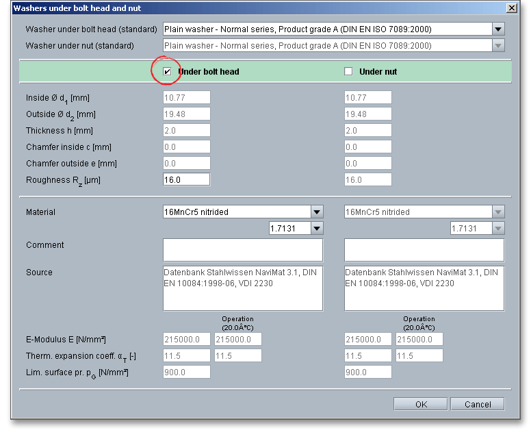
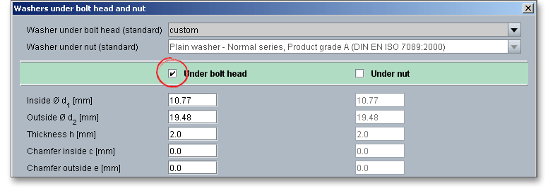
The program allows you to define your individual washer. Select the option ‘custom’ from the listbox. All input fields are activated and you can enter the values for your washer. Your inputs will be saved to the calculation file. Please be advised that changing the washer will delete your defined inputs and you have to enter the inputs again.
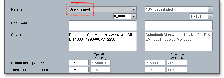
Select the material from the listbox. In case there is no material that will fulfill the design requirements, then simply define your individual material. Select the option ‘User-defined’ from the listbox and all inputs and options are enabled and you can specify your individual material very easily. Your inputs will be saved to the calculation file. Please be advised that changing the material will delete your defined inputs and you have to enter the inputs again.
The stiffnesses of the bolt as well clamped parts depend on the load introduction. If the axial working load \(F_{A}\) is introduced directly at the bolt head, then the load introduction factor is \(n = 1\). For the load introduction at the interface, the load introduction factor is \(n = 0\). The actual load introduction is between these two values.
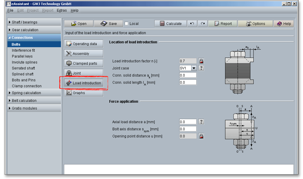
The load introduction factor \(n\) serves to convert the load introduction point at the single-bolted joints into the spring model and to allow for this load introduction point and is crucial for determining the size of the additional bolt loads. The factor is determined in accordance with VDI 2230. Depending on the load introduction point, a part of the clamped members is relieved, the other part is compressed. Thus the stiffness of the clamped parts changes as well as the elastic bolt length. The load introduction factor takes into account the stiffness changes. If the load introduction is not known, \(n\) is normally \(\approx 0,5\), in some cases \(n = 0\).
If transverse forces are transferred via frictional grip, the load introduction factor is \(n = 0\).
The VDI 2230 guideline provides six joint types according to the type of load introduction. The joint must be assigned to one of the joint types with regard to the position of the load introduction points. Care is to be taken to ensure that the interface lies in the marked region. This identifies the joint region which is evenly clamped and appropriate from the design point of view.

The force introduction point and thus the load introduction factor can be determined by the distance to the
connecting body \(a_{k}\) and the length of the connecting solid \(l_{A}\). The load introduction factor has a considerable effect
on the total stresses of the bolt and the residual clamp load. That’s why it is important to determine the load
introduction factor \(n\) as exactly as possible. The joint types SV 1, SV 2 and SV 4 are used for single-bolted
joints.
Please note: In the case of very small load introduction factors, it must be expected that the joint will possibly
tend to open. \(n = 0,4\) should be used for eccentrically clamped multi-bolted joints \(n = 0,4\).
Eccentrically clamped and eccentrically loaded bolted joints are most common. The line of action \(A-A\) of the load \(F_{A}\) does not lie in the bolt axis \(S-S\) and the bolt axis itself does not coincide with the axis \(0-0\) of the laterally symmetrical deformation body in the basic solid.
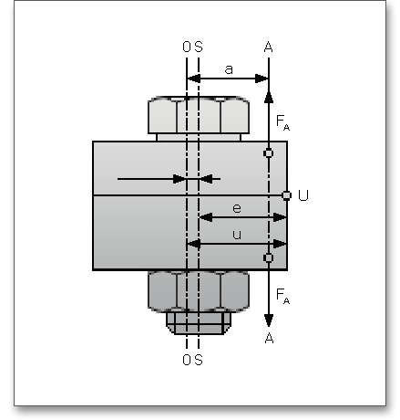
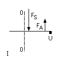
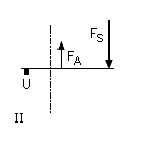
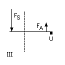
The distance a is the distance of the substitutional line of action of the axial working load from the axis of the laterally symmetrical deformation body. The distance \(a\) always has a positive sign. The distance \(s_{sym}\) is to be introduced with a positive sign if the force action line \(A\) and the bolt axis \(S\) lie on the same side relative to the axis \(0\) and with a negative sign if both are located on opposite sides. \(u\) is the edge distance of the opening point \(U\) from the axis of the imaginary laterally symmetrical deformation body. For the sign rule with regard to \(s_{sym}\), please see the following tables.
| Sign Rules According to VDI 2230-1: Tensile Working Load5
| ||||
| Loading case/variant
|  |  |  | |
| position of \(a\) and \(s_{sym}\) at 0 - 0 | ||||
| Dimensional ratios | on same side | |||
| \(a \le s_{sym}\) | \(a < s_{sym}\) | different sides
| ||
| \(s_{sym}\) | + | + | - | |
| Sign | u | + | - | +
|
| - The distance \(a\) of the substitutional line of action of the axial working
load is always positive.
| ||||
| Explanations | - Point U always lies at the outermost location of that side of the
interface which is at risk of opening and consequently point V lies at the
outermost location of the other side.
| |||
| - The distance \(v\) is always positive.
| ||||
| Sign Rules According to VDI 2230-1: Compressive Working Load5
| ||||
| Loading case/variant
| 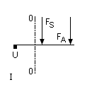 | 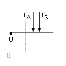 | 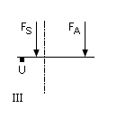 | |
| position of \(a\) and \(s_{sym}\) at 0 - 0 | ||||
| Dimensional ratios | on same side | |||
| \(a \le s_{sym}\) | \(a < s_{sym}\) | different sides
| ||
| \(s_{sym}\) | + | + | - | |
| Sign | u | - | - | - |
| - The distance \(a\) of a substitutional line of action of the axial working load
is always positive.
| ||||
| Explanations | - Point U lies at the outermost location of that side of the interface which
is at risk of opening and consequently point V lies at the outermost
location of the other side.
| |||
| - The distance \(v\) is always positive.
| ||||
| - Cases II and III can only lead to opening in exceptional instances.
| ||||
| - Case I is only illustrated for the sake of completeness; opening cannot
be expected.
| ||||
| 5 from: VDI 2230 Part 1, VDI Verlag, Duesseldorf 2015, p. 69, table 4. Sign rules
| ||||
The forces and displacements which occur in the bolted joint can be illustrated in principle by means of a joint diagram, such as the elongation of the bolt or pressing the parts together. The X-axis shows the elastic linear deformation \(f\) and the Y-axis shows the force \(F\). Click the button ‘Graphs’ to view the joint diagram. The joint diagram appears later in the calculation report.
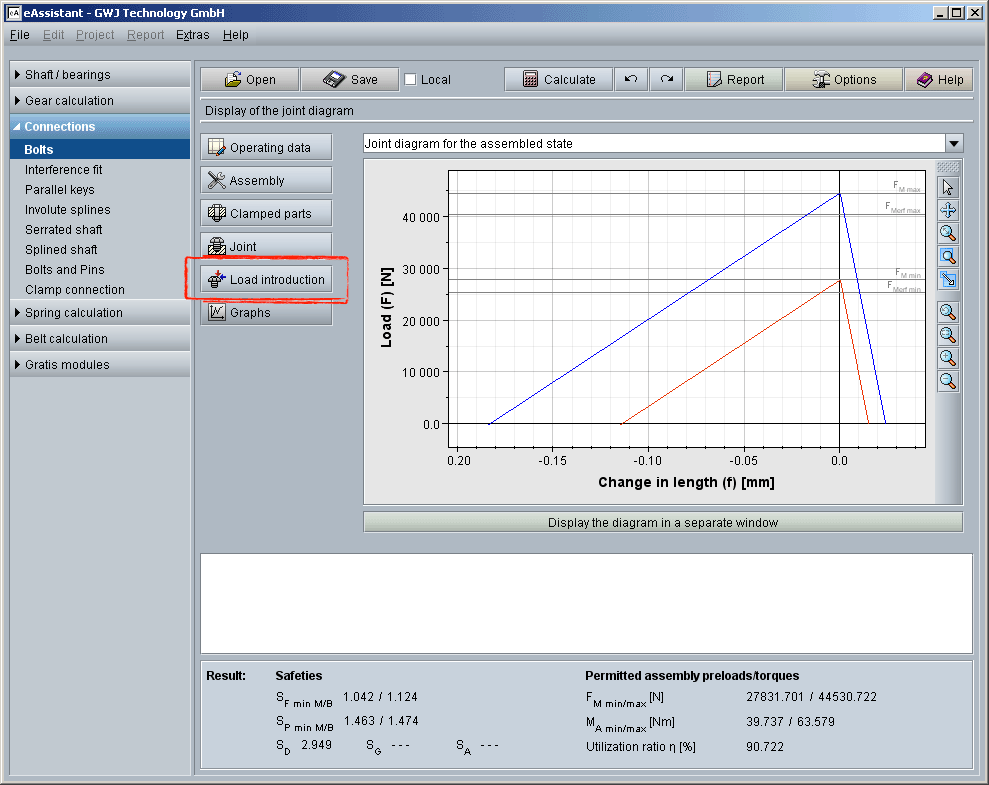
Click the listbox and select the joint diagram for the different working states:

Click the window ‘Display the diagram in a separate window’ and the joint diagram appears in an extra window. A toolbar is available on the right side. The toolbar provides additional options such as zoom or move functions to take a closer look at the joint diagram. You can use the function ‘Zoom’ to zoom in and out. If you use the function ‘Move’, you can change the position of the graphical representation.
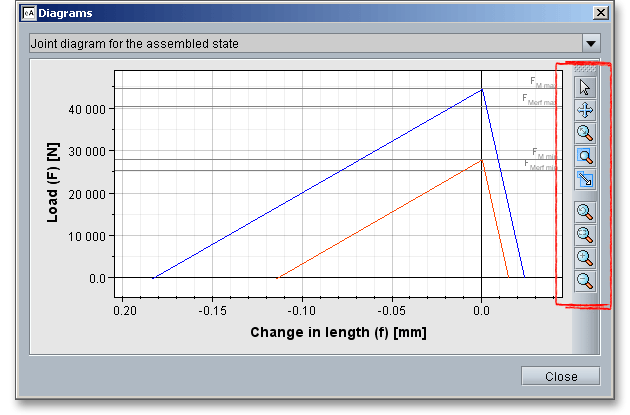
Please note: It may be quite helpful to display the joint diagram multiple times and to take a closer look at
different working states. To do so, click the button ‘Display the diagram in a separate window’ as many times as
you like. Now you can select the working state and compare it with each other. Even with a modified calculation
it is possible to compare the joint diagrams. Open the diagram in a new window and position the window next to
the calculation module. Click the ‘Redo’ button and ‘Undo’ button. You will immediately see the changes and you
can compare the different calculations.
|
| Reset selection: Click the arrow to disable the selection. |
|
| Move: You can move the joint diagram within the window. Click the move tool. While doing this, a small cross appears next to the mouse pointer. Click the window and hold down the left mouse button. Drag the mouse to move the diagram. |
|
| Zoom with the mouse: Just click a specific point and zoom in withthe mouse. |
|
| Zoom area: Enlarge a specific area. Draw a frame while holding down the left mouse button. After releasing the mouse button, the selected area will be enlarged. |
|
| Scale view: Scale the view vertically or horizontally. The height/width aspect ratio is not considered here. |
|
| Reset View: Click ‘Reset view’ to go back to the previous view. |
|
| Fit in window: Click the left mouse button to zoom out just enough so that you can see the entire diagram. |
|
| View zoom in: Click the left mouse button to enlarge the view. |
|
| View zoom out: Click the left mouse button to reduce the view. |
Several menu items are available from the context menu that is displayed when you right-click anywhere in the diagram.
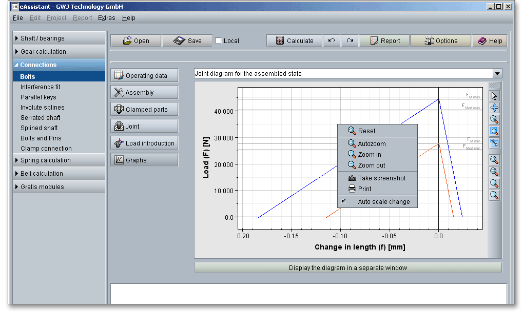
The following function are available here:
|
| Reset View: Click ‘Reset view’ to go back to the previous view. |
|
| Fit in window: Click the left mouse button to zoom out just enough so that you can see the entire diagram. |
|
| View zoom in: Click the left mouse button to enlarge the view. |
|
| View zoom out: Click the left mouse button to reduce the view. |
|
| Create a screenshot: Click this menu item to create a screenshot of the joint diagram. Enter the dimensions of the screenshot and click the button ‘OK’. The screenshot is copied into the clipboard. Click the menu item ‘Insert’ to paste the image into another program that has the ability to save it as an image file. |
|
| Print: The joint diagram can be printed. Click the menu item and select the right printer. |
Please note: To move the diagram, click in the diagram and hold down the right mouse button. Use the mouse
wheel to zoom the joint diagram in and out.
The calculation module provides a message window. This message window displays detailed information, helpful hints or warnings about problems. One of the main benefits of the program is that the software provides suggestions for correcting errors during the data input. If you check the message window carefully for any errors or warnings and follow the hints, you are able to find a solution to quickly resolve calculation problems.

The quick info tooltip provides additional information about all input fields and buttons. Move the mouse pointer over the input field or button, then you will get the additional information. This information will be displayed in the quick info line.

All results will be calculated during every input and will be displayed in the result panel. A recalculation occurs after every data input. Any changes that are made to the user interface take effect immediately. The result panel shows the safeties against the yield point \(S_{F}\), surface pressure \(S_{P}\), fatigue failure \(S_{D}\), slipping \(S_{G}\) and shearing off \(S_{A}\). Additionally, the preload, tightening torque as well as the utilization factor are displayed.

In case a minimum safety is not fulfilled, the result will be marked red. Press the Enter key or move to the next
input field to complete the input. Alternatively, use the Tab key to jump from field to field or click the ‘Calculate’
button after every input. Your entries will be also confirmed and the calculation results will displayed
automatically.
This results in the utilizing: \(\eta = max(\eta _{M}, \eta _{B})\)
The utilization factor quickly shows whether the bolted joint meets the requirements (\(\eta = 100\%\) or not \(\eta > 100\%\)).
The ‘Report’ button enables you to generate a calculation report.

The calculation report contains a table of contents. You can navigate through the report via the table of contents that provides links to the input values, results and figures. The report is available in HTML and PDF format. Calculation reports, saved in HTML format, can be opened in a web browser or in Word for Windows.
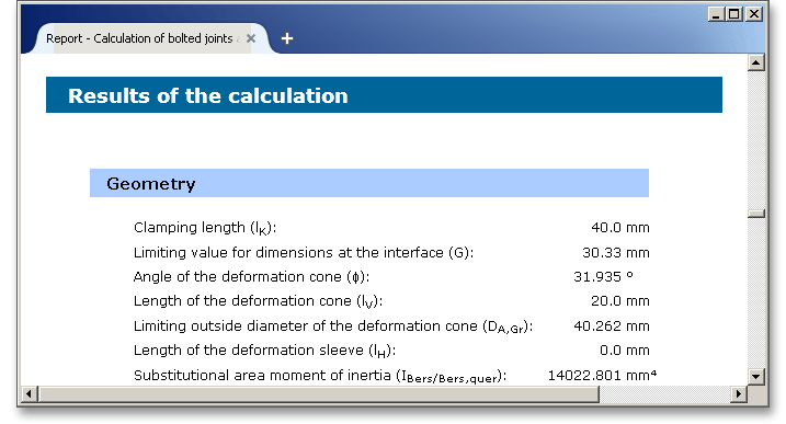
You may also print or save the calculation report:
When the calculation is finished, it is easy to save the calculation. You can save your calculation either to the eAssistant server or to your computer. Click on the button ‘Save’.

Before you can save the calculation to your computer, you need to activate the checkbox ‘Local’ in the calculation module. A standard Windows dialog for saving files will appear. Now you will be able to save the calculation to your computer.

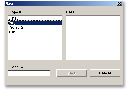
In case you do not activate the option in order to save your files locally, then a new window is opened and you can save the calculation to the eAssistant server. Please enter a name into the input field ‘Filename’ and click on the button ‘Save’.
The ‘Undo’ button allows you to reset your inputs to an older state. The ‘Redo’ button reverses the undo.

Click on the ‘Options’ button in the menu bar at the top to change some general settings, e.g. the unit system or the minimum safeties.

Here you can change the following settings:
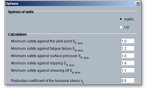
The pre-defined minimum safeties are given in VDI 2230 Part 1. The safety margin is to be established by the user. VDI 2230 provides the following safety values: