Please login with your user name and your password. To start the calculation module for timing belts, please click the menu item ‘Belt calculation’ on the left side and then select ‘Timing belt’. The calculation module allows to calculate a complete belt drive. The module supports a graphical and interactive definition of the belt drive. The calculations are based on the publication ‘Zahnriemengetriebe - Eigenschaften, Normung, Berechnung, Gestaltung, Nagel, Hanser Verlag 2008’. The module was developed in a close cooperation with Mr Dr. Thomas Nagel (Dresden University of Technology) and offers for the first time a calculation method independently of a certain manufacturer. The eAssistant module is the first calculation program that enables the dimensioning of multiple shaft gear drives in all types of profiles that are usual in the market. The eAssistant software module offers an easy-to-use and intuitive interface. The attractiveness of this module is additionally enhanced by the possibility to choose from several solution variants and to compare different solutions to each other. The timing belt calculation is basically arranged in three main operating fields:
The timing belt drive is classified in the group of transmission drives and consists of a timing belt and at least two timing belt pulleys.

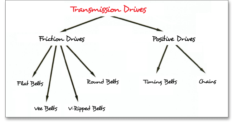
The profile geometry of belt and pulley is designed to perfectly match each other. The profile geometry is identified by an abbreviation (e.g., HTD, STD or AT) and the drives are offered in various pitches. The timing belt pitch refers to the center-to-center distance between the center of one tooth on a timing belt pulley to the center of the adjacent tooth. Timing belt drives can be classified according to:
Timing belt drives have advantages and disadvantages compared to other power transmission drives:
The calculation of the timing belt profile starts with the definition of the drive task as well as with the pre-selection of the belt type. Open the calculation module in order to add the power data. To select an appropriate belt, enter the desired diameter for the drive pulley. You can pre-select either the drive power, torque or tangential force. To do so, activate the radio button next to the input field. Then the input field will be enabled and you can add your input value. The other sizes in each case are automatically calculated. Press the Enter key or use the Tab key to confirm your entries. Click the ‘Calculate’ button after every input. Your entries will be also confirmed. Use the listbox to select the engine starting torque and operating time.
By using the checkboxes shown on the right-hand side, you can make further restrictions with regard to the pitches depending on the drive task. Otherwise, all pitches are used.
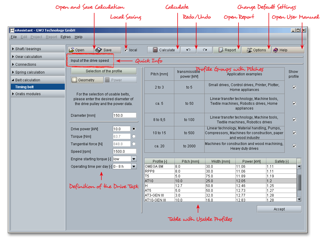
Once you have entered diameter, drive power and speed, you are provided with an overview of all belts suitable for your application. Click the button ‘Accept’ in order to confirm the selected belt and to used it for the calculation.

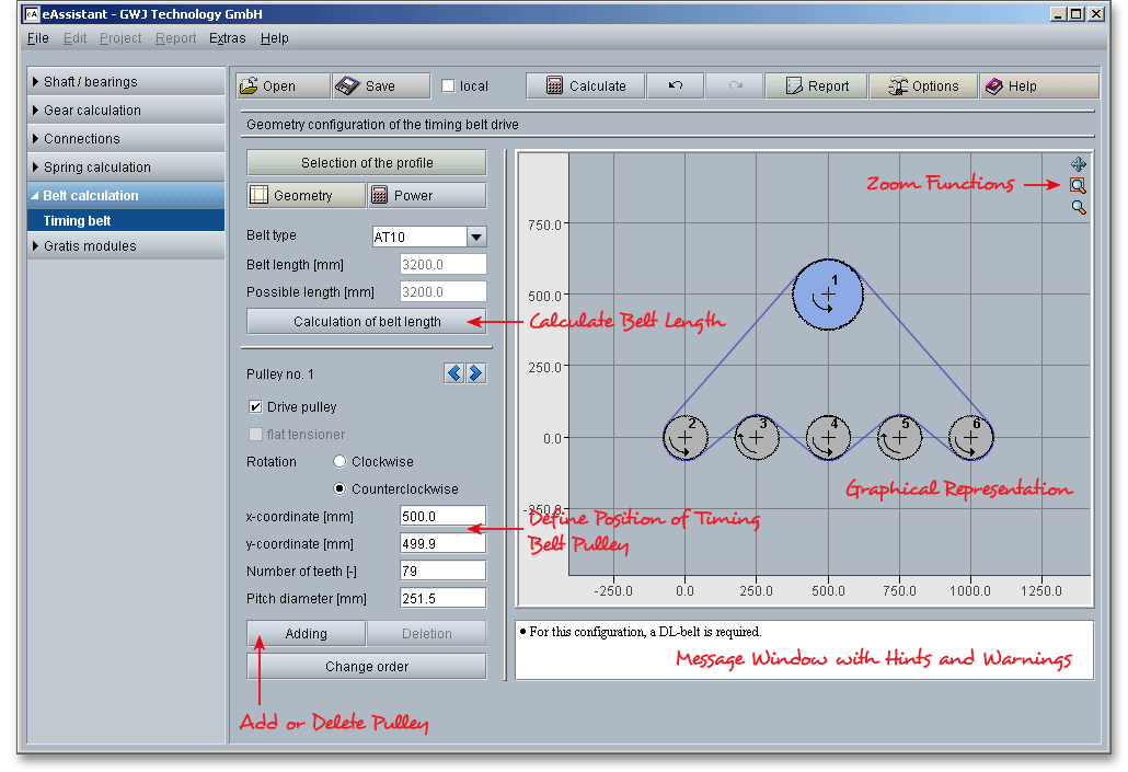
If you have selected a profile, then click the button ‘Accept’ to get to the configuration of the geometry. In this section, you can define the number of teeth or add drive pulleys or tensioners. A multiple shaft gear drive with any number of timing belt pulleys and tensioners is possible. The geometry section contains a graphic representation. The main view reveals the configurated timing belt drive. Here you can use the mouse to select and position the timing belt pulleys.
The listbox ‘Belt type’ provides the belt type that has been selected before from the table. The pre-selection of
the belt is initially based on a simple two-shaft drive. In case, the determined safeties are not enough
for the application, then it is recommended to select another belt type or to define another belt
width.
Here you can see the belt length of the configuration. If you adjust the position of the timing belt pulley by clicking and dragging with your mouse or if you change the position by entering x-coordinates or y-coordinates, the belt length is always automatically determined.

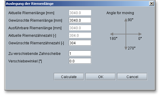
The calculation program provides a simple solution for the dimensioning of the belt length. You can change the position of the timing belt pulley so that the belt length and the required belt length match exactly. Another window opens when you click on the ‘Calculation of belt length’ button. Here is where you can position the timing belt pulley so that you will get your desired belt length. The timing belt pulley that is currently selected in the graphic representation is the timing belt pulley you can move. But the input field ‘Pulley for moving’ allows you to select another timing belt pulley. The angle of moving indicates the direction in which the timing belt pulley should be moved in order to adjust the belt length to the desired belt length. The graphic representation on the right-hand side displays how the angle of moving is defined. Clicking the button ‘Calculate’ adjusts the position of the selected timing belt pulley. Click the button ‘OK’ in order to apply the belt length.
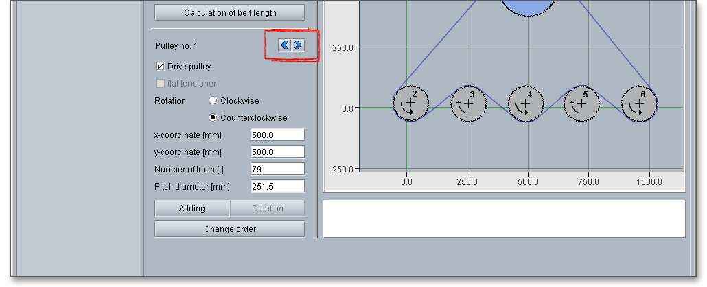
A belt drive requires a timing belt and at least two timing belt pulleys. The geometry of the timing belt pulleys must be precisely matched. A simple two-shaft or a multiple shaft belt drive with any number of timing belt pulleys or tensioners can be defined. By means of the two arrows to the right and left next to ‘Pulley No.’, the timing belt pulleys are selected one after the other (either clockwise and counter-clockwise). But you can also click the timing belt pulley to quickly choose a pulley. A colored marking points to the currently selected timing belt pulley. For a better orientation, the timing belt pulleys are numbered. The numbering sequence also determines the rotation of the timing belt in the belt drive. The ‘Power’ section determines the safety for every timing belt pulley.
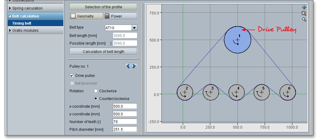
In using the ‘Drive pulley’ checkbox, you determine which timing belt pulley is the drive pulley of the belt drive.
Only one timing belt pulley can be the drive at any one time. By clicking on the checkbox, you activate the
currently selected timing belt pulley as drive. In the graphic repesentation, the drive pulley is highlighted in
blue.
The option ‘Rotation’ is for establishing the direction of rotation of the timing belt pulley. There are two possibilities for you here: clockwise and counter-clockwise. An arrow marks the direction of rotation of the timing belt pulleys.
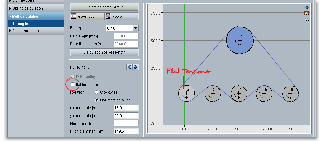
Timing belts require a pre-tension load using a tensioning system if the gearing has a fixed centre distance or the belt can not be held by a change in the distance of the shaft. The design ranges from simple pulleys to automatically operating tensioning systems. A flat tensioner keeps the pre-tension load constant and is often used in industrial applications. The tensioner can be either on the toothed side or on the belt back. The tensioner is often arranged inside. Thus, the belt is loaded with only swelling bending loads but not with alternating bending loads. If an internally positioned tensioner running on the belt is designed as a flat tensioner, then it must have a larger diameter than a comparable toothed pulley.
| Minimum Sizes of Flat and Toothed Tensioners3
| ||||
| Timing Belt Profile | Timing Belt Basic Material | Number of Teeth of Toothed Tensioner, Internal | Diameter of Flat Tensioner, External [mm] | Diameter of Flat Tensioner, Internal [mm] |
|
| PU Polyurethane |
|
|
|
|
| CR Rubber Elastomer |
|
|
|
| T2; T2.5 | PU | 10 | 15 | 15 |
| AT3 | PU | 15 | 20 | 20 |
| T5 | PU | 10 | 30 | 30 |
| AT5 | PU | 15 | 60 | 25 |
| T10 | PU | 12 | 60 | 60 |
| AT10; ATP10 | PU | 15 | 120 | 50 |
| T20 | PU | 15 | 120 | 120 |
| AT20 | PU | 18 | 180 | 120 |
| GT2-8MR | PU | 22 | Do not use | 100 |
| GT2-14MR | PU | 28 | Do not use | 175 |
| GT3-2MR | CR | 10 | From approx. 6,5 | From approx. 25 |
| HTD3M; GT3-3MR | CR | 9 | From approx. 10 | From approx. 40 |
| HTD5M; GT3-5MR | CR | 14 | From approx. 22 | From approx. 65 |
| HTD8M | CR | 18 | From approx. 50 | From approx. 100 |
| HTD14M | CR | 28 | From approx. 125 | From approx. 180 |
| HTD20M | CR | 34 | From approx. 220 | From approx. 250 |
| 3 Nagel, Thomas: Zahnriemengetriebe, 2008, Carl Hanser Verlag, p. 73, table 4.3
| ||||
Here you can indicate the position of the timing belt pulleys. There are two possiblities for you here:
Move the timing belt pulley by changing the x and y-position: You can enter the position of the timing belt pulley directly via the input fields of ‘x-coordinate’ and ‘y-coordinate’.

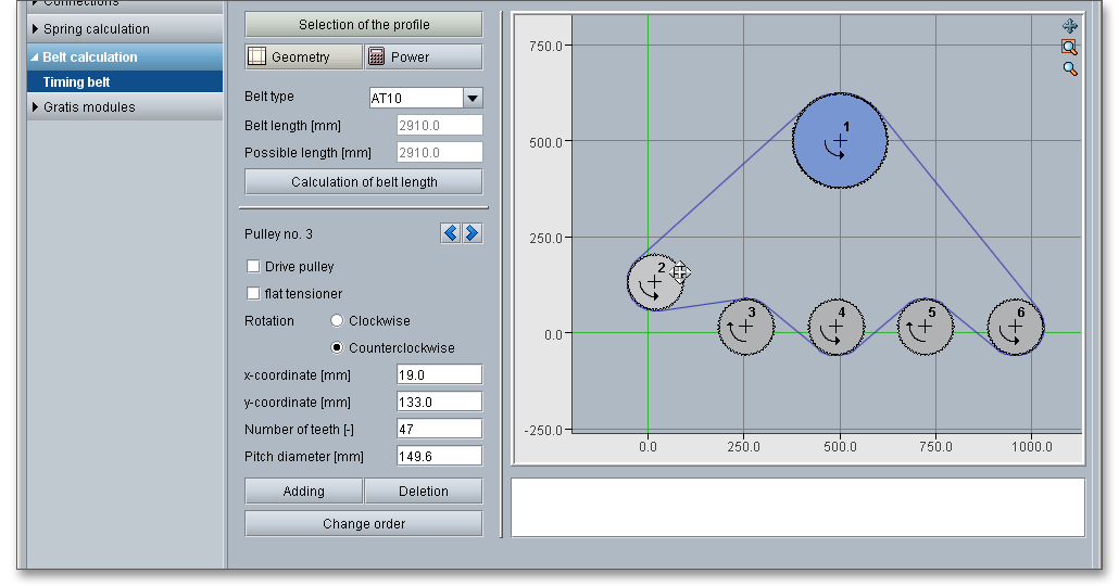
Please note: If you change the position of the timing belt pulley, the belt automatically follows the
course.
For a multiple shaft gear drive or if there is counterbending of the belt by using a tensioner on the outside, the
minimum number of teeth needs to be further increased.
Please note: The number of teeth of the timing belt pulleys should not be too small. The following table provides
some values for the minimum number of teeth \(z_{min}\) per profile group.
| Values for Minimum Number of Teeth \(z_{min}\)4
| ||
| Pitch \(p_{b}\) [mm] | Minimum Number of Teeth \(z_{min}\) with Counterbending (without Counterbending)
| |
| Trapezoidal Profiles | High Power Profiles | |
| 2 ... 7 | 18 (10) | 18 (12) |
| \(>\) 7 ... 10 | 20 (12) | 22 |
| \(>\) 10 ... 19 | 22 (14) | 28 |
| From 20 | 25 (18) | 34 |
| 4 Nagel, Thomas: Zahnriemengetriebe, 2008, Carl Hanser Verlag, p. 94, table 5.1
| ||
This is where you define the pitch diameter of the timing belt pulley. The input of the pitch diameter and the number of teeth is synchronous as both are appropriately linked via the belt pitch. This means on changing the pitch diameter you also equivalently change the number of teeth.

By clicking on the button ‘Adding’, you can add another timing belt pulley. The new timing belt pulley is always
inserted after the currently selected one and gets automatically a number. By clicking the ‘Deletion’ button, you
delete the currently selected timing belt pulley.
Please note: Select a timing belt pulley and press the Delete key of your keyboard in order to delete the timing
belt pulley. Another possibility is to click the right mouse button to open a new context menu. Select ‘Delete’ from
the context menu.

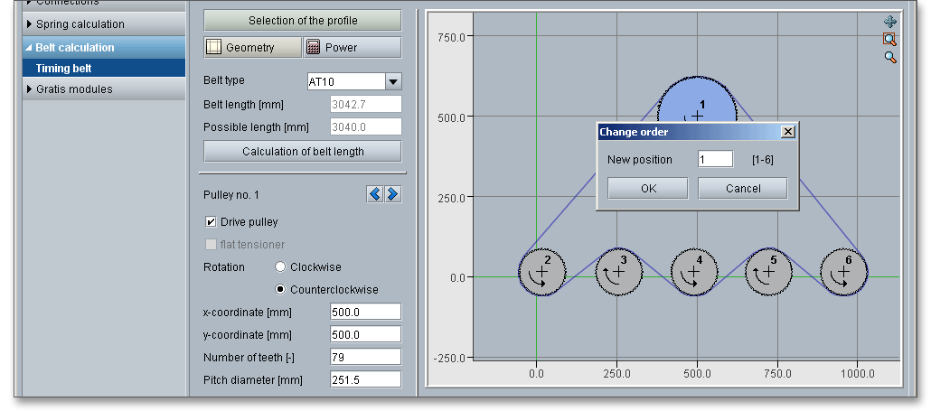
Clicking the button ‘Change order’ allows you to change the order of the timing belt pulleys. Choose the timing belt pulley and click ‘Change order’. A new window is opened and you can change the position of the selected pulley. Confirm with ‘OK’ and the new order of the timing belt pulleys is included in the configuration of the drive, the other pulleys and the belt will be automatically adapted to the new order.
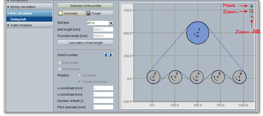
There are several ways to look closely at the configuration of your timing belt drive and to get the view that you need. Click the ‘Zoom’ icon to zoom in and out. Click the ‘Move’ icon to move the graphic representation to a new position.
You can use the ‘Move’ function to move the graphical representation of the entire timing belt drive anywhere in the window. In order to activate this functionality, please click the ‘Move’ symbol. The mouse pointer changes to a cross to show that the representation can now be moved. Click in the window and hold the left mouse button, drag the representation to its new position. When you release the mouse button, you can see the original mouse pointer again and the function is disabled.
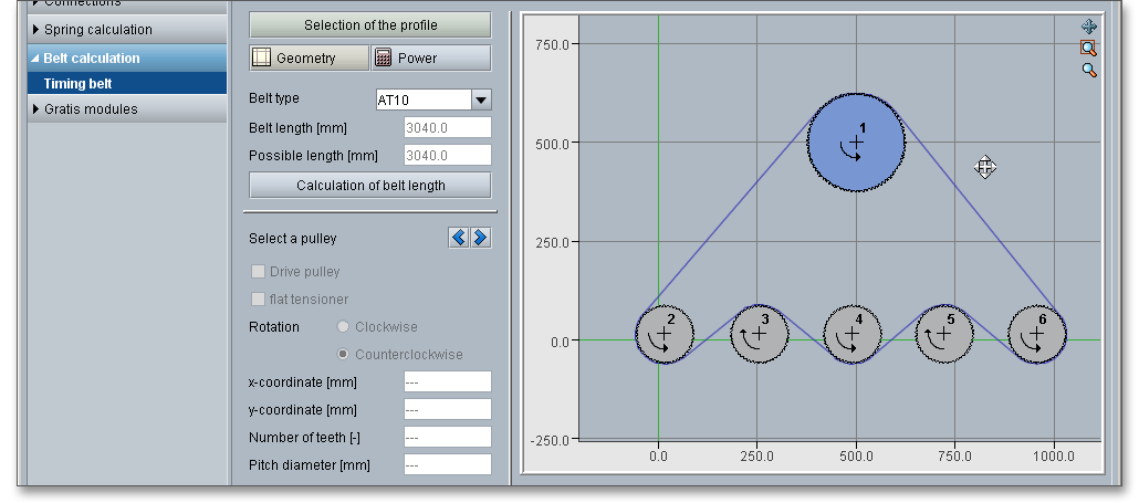
By using this function, you can zoom in to show details of the configuration. Click on the symbol and drag the mouse pointer diagonally until you have drawn a box around the area you want to enlarge. Select ‘Zoom all’ so that the configuration fills the window.
The ‘Zoom all’ functionality enables you to return to the original display of the configuration so that the whole
configuration fits in the window again.
Please note: Clicking the right mouse button opens a context menu containing the ‘Zoom’ and ‘Zoom all’
functions.

The calculation module for timing belts offers additional functions. One right click opens the context menu with
all operations available for the selected item such as copy, cut, insert, delete and zoom.
It is very easy to copy and insert a timing belt pulley. This is especially useful if several timing belt pulleys have the same number of teeth and the same diameter. Click on the timing belt pulley to be copied. Right-click with the mouse and select ‘Copy’ from the context menu.

Now position the cursor where you want to insert the timing belt pulley and click the right mouse button. Select
‘Insert’ from the context menu. The copied timing belt pulley is placed and gets a number. You can change the
position of the timing belt pulley by clicking and dragging with your mouse or by entering the x-coordinates and
y-coordinates.
In order to cut a timing belt pulley, select the pulley to be cut and click the right mouse button to open the context menu. Choose the menu item ‘Cut’.

Now place the mouse pointer where you want to insert the timing belt pulley and click the right mouse button.
Select ‘Insert’ from the context menu. The cut timing belt pulley is placed. You can change the position of the
timing belt pulley by clicking and dragging with your mouse or by entering the x-coordinates and
y-coordinates.
Select the timing belt pulley and click the right mouse button. Select the entry ‘Delete’ from the context menu. If you want to delete the entire belt drive, then select the menu item ‘Delete all’ from the context menu.

The calculation module provides a message window. This message window displays detailed information, helpful hints (e.g., DL belt required) or warnings about problems. On having configured, for instance, a belt drive where the belt crosses or timing belt pulleys touch or the safety is below the minimum safety, then warnings appear in the message window. One of the main benefits of the program is that the software provides suggestions for correcting errors during the data input. If you check the message window carefully for any errors or warnings and follow the hints, you are able to find a solution to quickly resolve calculation problems.

The quick info tooltip provides additional information about all input fields and buttons. Move the mouse pointer over the input field or button, then you will get the additional information. This information will be displayed in the quick info line.

In using the ‘Power’ button, you can start the power calculation of the timing belt drive. The power calculation is based on ‘Zahnriemengetriebe - Eigenschaften, Normung, Berechnung, Gestaltung’, Nagel, Hanser Verlag 2008. The transferable power is determined for all timing belt pulleys.
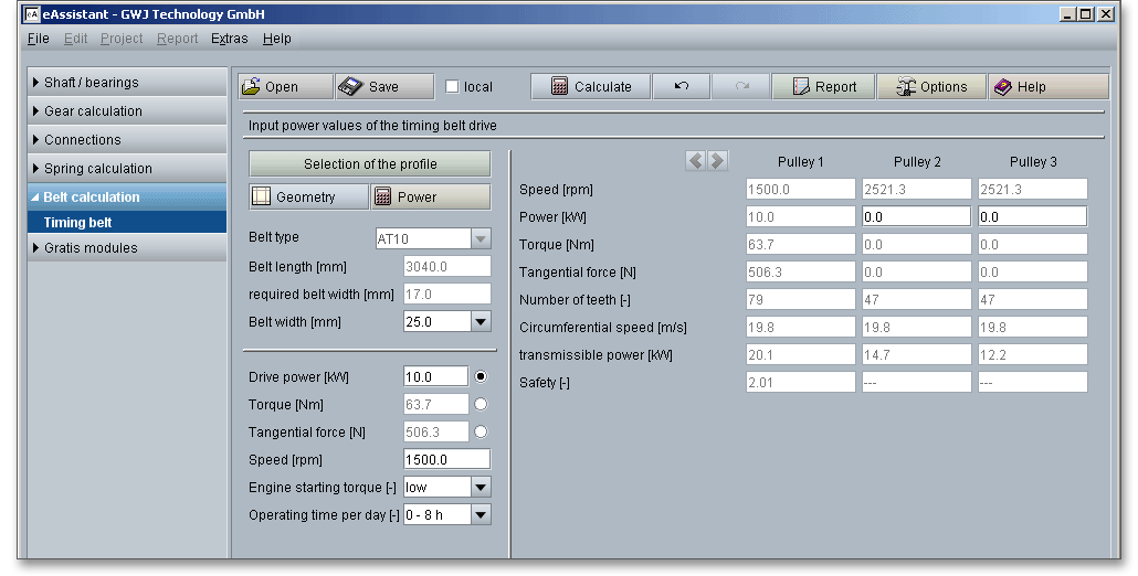
This in conjunction with the inputted power data determines the safety factor for the timing belt pulley
concerned. You are provided with an overview of all relevant data for the power transmission of the timing belt
pulleys. The tooth load capacity is an important factor for timing belt drives focusing on the transmissible power
and/or torques in the smallest possible installation space. Due to different rating life values and test conditions, a
comparison of power data of a specific timing belt profile from different manufacturers is not possible. Each
product manufacturer has its own specific requirements. The power data of the timing belts are manufacturer
specific. You are provided with an overview of all relevant data for the power transmission of the timing belt
pulleys. The power of the drive pulley has a positive sign, the other timing belt pulleys have a negative
sign.
The determination of the required belt width is based on the defined minimum safety. Click the button ‘Options’ to modify the factor for the minimum safety. The listbox ‘Belt width’ provides all common standard belt widths. so you can easily choose another belt width. In case you select a belt width that is too small and the safety is below the minimum safety, then an appropriate message will be displayed in the message window. In addition, the safety is marked red.

The following table provides specific values for the belt width. You can find these values in the calculation module:
| Standard Belt Width for Timing Belts Made of Rubber Elastomer5
| |||
| Profile | Standard Width \(b_{s}\) in mm | Profile | Standard Width \(b_{s}\) in mm |
| GT3-2MR | 3/6/9 | GT3-3MR | 6/9/15 |
| GT3-5MR | 6/9/15/20/25/30 | GT2-8MGT | 20/30/50/85 |
| GT2-14MGT | 40/55/85/115/170 | HTD3M | 6/9/15 |
| OMEGA-3M | 6/9/15 | HTD5M | 9/15/25 |
| OMEGA-5M | 9/15/25 | HTD8M | 20/30/50/85 |
| RPP8 | 20/30/50/85 | OMEGA-8M | 20/30/50/85 |
| HTD14M | 40/55/85/115/170 | OMEGA14M | 40/55/85/115/170 |
| HTD20M | 115/170/230/290/340 | MXL | 3.2/4.8/6.4 |
| XL | 6.4/7.9/9.5 | L | 12.7/19.1/25.4 |
| H | 19.1/25.4/38.1/50.8/76.2 | XH | 50.8/76.2/101.6/127 |
| 5 Nagel, Thomas: Zahnriemengetriebe, 2008, Carl Hanser Verlag, p. 103, table 5.7
| |||
| Standard Belt Width for Timing Belts Made of Polyurethane6
| |||
| Profile | Standard Width \(b_{s}\) in mm | Profile | Standard Width \(b_{s}\) in mm |
| T2 | 4/6/10/16/25/32 | T2,5 | 6/10/16/25/32 |
| T5 | 6/10/16/25/32/50/75/100 | T10 | 16/25/32/50/75/100/150 |
| T20 | 32/50/75/100/150 | AT3 | 6/10/16/25/32 |
| AT5 | 6/10/16/25/32/50/75/100 | AT10 | 16/25/32/50/75/100/150 |
| AT20 | 32/50/75/100/150 | AT3-GENIII | 6/10/16/25/32 |
| AT5-GENIII | 6/10/16/25/32/50/75/100 | AT10-GENIII | 16/25/32/50/75/100/150 |
| ATP10 | 16/25/32/50/75/100/150 | ATP15 | 25/32/50/75/100/150 |
| 6 Nagel, Thomas: Zahnriemengetriebe, 2008, Carl Hanser Verlag, p. 103, table 5.7
| |||
The total safety factor \(S_{ges}\) (\(S_{ges} = S_{1} + S_{2} + S_{3}\)) takes into account the possible shock loads depending on the starting torque of the motor as well as gearboxes with transmissions into higher speeds and the operating time per day.
| Reference Values for the Safety Factors7
| ||
| Safety | S\(_{1}\) = 1.2 for motors with low starting torque | Considers type of |
| S\(_{1}\) | S\(_{1}\) = 1.5 for motors with medium starting torque | driving machine high and |
| S\(_{1}\) = 1.8 for motors with high starting torque | shock loads when starting | |
| Safety | S\(_{2}\) = 0 for transmissions \(i\) \(>\) 0.8 | Considers transmissions |
| S\(_{2}\) | S\(_{2}\) = 0.1 for transmissions 0.6 \(<\) \(i \leq \) 0.8 | into higher speed |
| S\(_{2}\) = 0.2 for transmissions 0.4 \(<\) \(i \leq \) 0.6 | ||
| S\(_{2}\) = 0.3 for transmissions 0.2 \(<\) \(i \leq \) 0.4 | ||
| S\(_{2}\) = 0.4 for transmissions \(i \leq \) 0.2 | ||
| Safety | S\(_{3}\) = 0.1 for daily operating time up to 8 hours | Considers continuous operation |
| S\(_{3}\) | S\(_{3}\) = 0.2 for daily operating time up to 16 hours | per day |
| S\(_{3}\) = 0.4 for daily operating time over 16 hours | ||
| 7 Nagel, Thomas: Zahnriemengetriebe, 2008, Carl Hanser Verlag, p. 96, table 5.2
| ||
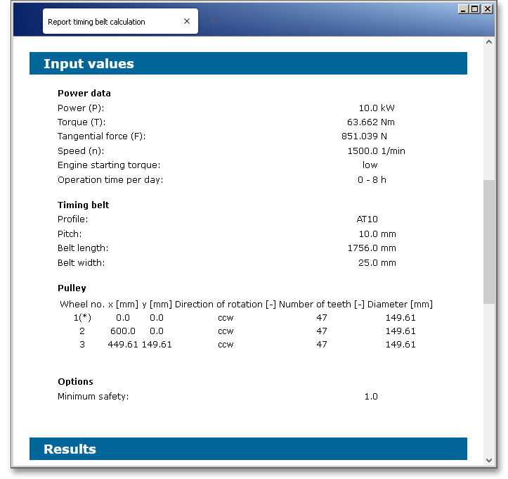
After the completion of your calculation, you can create a calculation report. Click on the ‘Report’ button to open the calculation report.

The calculation report contains a table of contents. You can navigate through the report via the table of contents that provides links to the input values, results and figures. The report is available in HTML and PDF format. Calculation reports, saved in HTML format, can be opened in a web browser or in Word for Windows. You may also print or save the calculation report:
When the calculation is finished, it is easy to save the calculation. You can save your calculation either to the eAssistant server or to your computer. Click on the button ‘Save’.

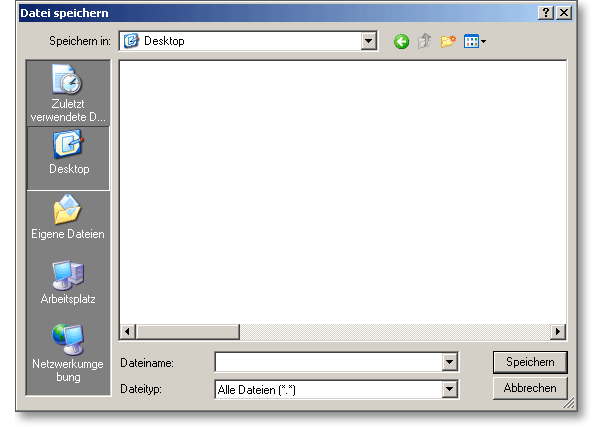
Before you can save the calculation to your computer, you need to activate the checkbox ‘Local’ in the calculation module. A standard Windows dialog for saving files will appear. Now you will be able to save the calculation to your computer.
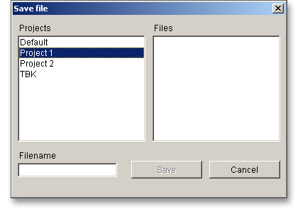
In case you do not activate the option in order to save your files locally, then a new window is opened and you can save the calculation to the eAssistant server. Please enter a name into the input field ‘Filename’ and click on the button ‘Save’.
The ‘Undo’ button allows you to reset your inputs to an older state. The ‘Redo’ button reverses the undo.

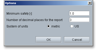
Click on the button ‘Options’ in the top menu bar of the eAssistant software to modify some general settings.

Change the unit system, the factor for the minimum safety or the number of decimal places in the calculation report.
