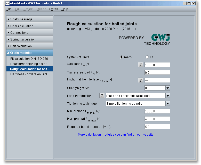
A bolted joint is a typical connection of two or more parts that are held together by a bolts. The main function of the bolts is to transmit the forces and moments between the connected parts. The minimum bolt diameter can be roughly determined according to the VDI 2230 guideline. The guideline VDI 2230 is one of the common methods of design used for bolted joints. VDI 2230 applies to steel bolts in high-duty and high-strength bolted joints (for strength grades 8.8 to 12.9) and a frictional transmission of the working load. The working load consists of a static or dynamic axial load. In addition, bending moments and transverse loads may occur.

With entering the maximum axial load and/or transverse load, the mimimum and maximum preload as well as minimum bolt diameter can be estimated. For the estimation of the transverse load, the friction value is taken into consideration at the interface.
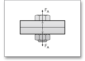
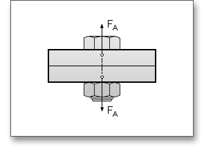
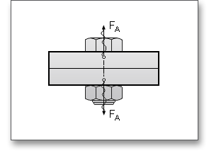
Axial force \(F_{A}\) is an operating force directed in bolt axis and acting proportionally on a bolt.
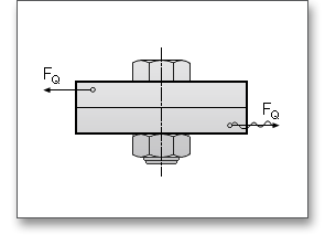
The transverse load \(F_{Q}\) is a load applied perpendicularly to the bolt axis.
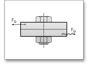
Bolted joints are designed that the transverse loads are transmitted to the interface of a preload joint by static friction. It is also possible that the connecting elements (fit bolts, pins, sleeves) transmit transverse loads in a positive manner. Please click the ‘Question mark’ button next to the friction coefficient in order to open the following table. This table shows approximate values for the static friction coefficients at the interface:
| Approximate Values for Static Friction Coefficients at the Interface According to VDI 22301
| ||
| Material Combination | Static Friction Coefficient in the State | |
| Dry | Lubricated | |
| Steel - Steel/Cast Steel | 0.1 to 0.23 | 0.07 to 0.12 |
| Steel - Gray Cast Iron | 0.12 to 0.24 | 0.06 to 0.1 |
| Gray Cast Iron - Gray Cast Iron | 0.15 to 0.3 | 0.2 |
| Bronze - Steel | 0.12 to 0.28 | 0.18 |
| Gray Cast Iron - Bronze | 0.28 | 0.15 to 0.2 |
| Steel - Copper Alloy | 0.07 | - |
| Steel - Aluminum Alloy | 0.1 to 0.28 | 0.05 to 0.18 |
| Aluminum - Aluminum | 0.21 | - |
| 1 Table from: VDI 2230, Part 1, February 2003: Systematic Calculation of High Duty Bolted
Joints, Joints with One Cylindrical Bolt, Table A6, Approximate Values for Static Friction
Coefficients, p. 114
| ||
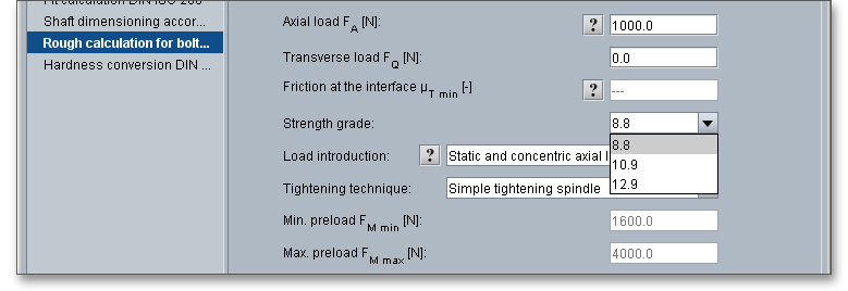
The calculation module takes three strength grades into consideration: 8.8, 10.9 and 12.9. The strength grades describe the properties of a bolt (e.g., hardness, tensile strength \(R_{m}\) and yield point \(R_{e}\)). The most common grade for bolted joints is grade 8.8. The strength grades 10.9 and 12.9 are used in particular for preloaded bolted joints.
The following options for the selection of the load introduction are available:
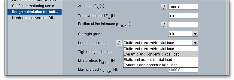
Clicking the ‘Question mark’ button next to the listbox opens a new window showing an illustration of the load introduction.

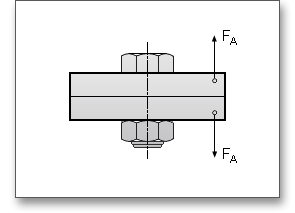
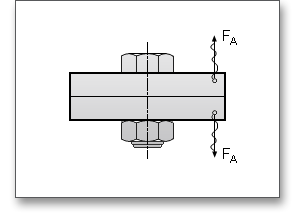
The tightening technique may influence the required dimensions of the bolt and must be carefully considered. Select the following tightening techniques from the listbox:
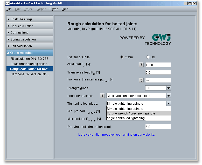
During the assembly of the joint, a preload \(F_{M}\) is produced and this produces a clamp load \(F_{K}\). \(F_{Mmin}\) is the required
minimum assembly preload which can occur at \(F_{Mmax}\) resulting from inaccuracies in the tightening technique and
maximum friction. \(F_{Mmax}\) is the maximum preload for which a bolt must be designed so that, in spite
of inaccuracies in the tightening technique, the required clamp load in the joint is produced and
maintained.
Clicking the link ‘More calculation modules’ leads you to our web site. Here you can register for a free test account in order to use all eAssistant calculation modules (e.g., shafts, cylindrical gears, bevel gears, springs). Find more information in section 2 ‘Registration’).
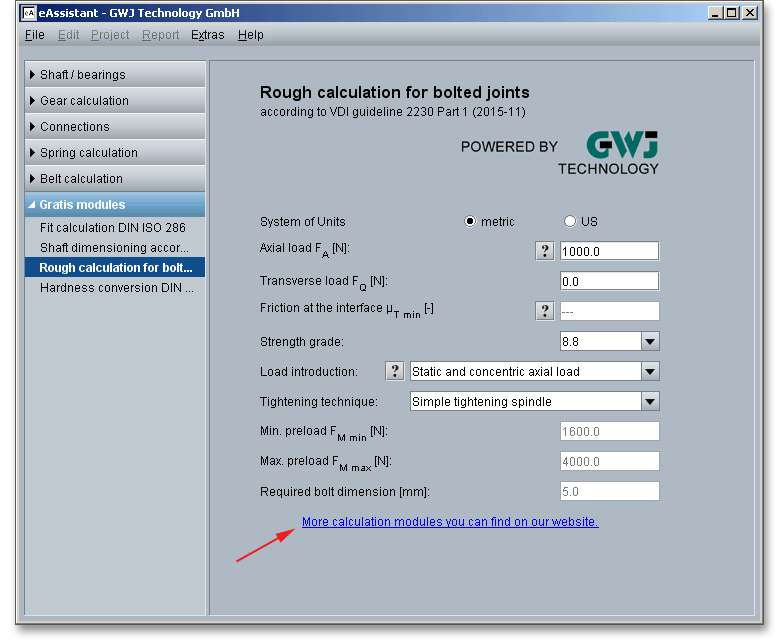
Please Note: If you registrate for the first time, you will receive a password in order to login. The project management helps you to start the calculation modules. The list on the left side shows all calculation modules including the free modules. If you use these modules, then no time will be deducted from your account.
Our manual is improved continually. Of course we are always interested in your opinion, so we would like to know what you think. We appreciate your feedback and we are looking for ideas, suggestions or criticism. If you have anything to say or if you have any questions, please let us know via telephone +49 (0) 531 129 399-0 or email www.eAssistant.eu.