Celler Straße 67 - 69
38114 Braunschweig
Germany
Fon: +49 (0) 531-129 399 0
Fax: +49 (0) 531-129 399 29
Mail: info@eassistant.eu
Web: http://www.gwj.de
Planetary gear trains according to DIN 3960, DIN 3990, ISO 6336 and further standards
Features
- Planetary stages with any number of planet gears
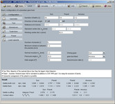
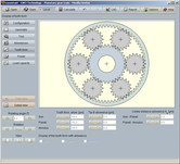
- Easy configuration to find fast solutions to dimension planetary gear trains including display of transmission ratio and standard centre distances
- Different drive configurations are possible
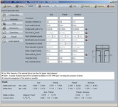
- Check of symmetric arrangement of planet gears according to same pitch and minimum distance between the planet gears
- Suggestion for an unsymmetric arrangement of planet gears
- Geometry of cylindrical gear pairs according to DIN 3960, DIN 3961, DIN 3964, DIN 3967, DIN 3977 and DIN 868
- Consideration of profile shift modification including dimensioning function for balanced specific sliding
- Allowances for tooth thickness and centre distance can be selected from a listbox or can be individually defined
- Addendum chamfer can be considered in the calculation
- Standardized basic rack profiles for tools according to ISO 53, DIN 867 and DIN 3972 can be selected or individually defined, protuberance tools with or without allowance, dimensioning function for special basic rack profiles
- Type of tool: hob, gear shaper cutter and constructed involute
- Determination of test dimensions for the gearing
- Determination of tooth thickness allowances from measured values and given test dimensions
- Check for meshing interferences on the basis of the accurate gear tooth form
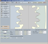
- Display of the gear tooth form including animation/simulation of the tooth mesh
- Parallel representation and animation of tooth mesh for sun/planet and planet/annulus
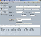
- Calculation of the load capacity according to DIN 3990 Method B, ISO 6336 Method B and ISO/TR 13989 (scuffing) with integrated material and lubricant database
- Calculation of load capacity with load spectrum according to ISO 6336 Part 6, determination is based on the Palmgren-Miner rule: load-dependent K-factors are calculated for each torque class; safeties are determined by way of iteration until the sum of damage parts is obtained
- Diagram of flash temperature (contact temperature)
- Calculation of torques, speeds including relative speed of the planet gear as well as power, pitch power and coupling power
- Consideration of grinding notches in the load capacity calculation
- Optimal hardening depth, manual input of hardening depth and consideration in the load capacity calculation
- Selection of mode of operation is possible for swelling, alternating or oscillating
- Calculation of tangential force of the planet carrier as well as centrifugal force of the planet
- Determination of face coefficients KHß according to DIN 3990 T1 Method C
- Calculation of safeties for fatigue or limited life strength and static strength (tooth root, flank/pitting, scuffing)
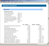
- Detailed calculation report in HTML and PDF format
- Output of CAD data via eAssistant CAD plugins or DXF interface
Description
This gear calculation module allows a fast and easy calculation of planetary gear trains with any number of planet gears. There are different drive configurations possible. The configuration part of the module provides a fast solution regarding special requirements. By choosing the number of teeth and a selected drive configuration, the transmission ratio is immediately determined. Furthermore, the standard centre distances of cylindrical gear pairs sun/planet and planet/annulus are displayed. The working centre distance can be defined. The symmetric arrangement of planet gears and the defined minimum distance are checked. If a symmetric arrangement of planet gears is not possible, a suggestion for an unsymmetric arrangement will be displayed.
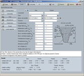
The geometry calculation of the cylindrical gears is based on DIN 3960, DIN 3961, DIN 3964, DIN 3967, DIN 3977 and DIN 868. Profile shift modification, addendum chamfer and allowances will be taken into consideration. Allowances of tooth thickness and centre distance can be comfortably selected from listboxes. For the profile shift modification factor, an dimensioning function for balanced specific sliding is available. Different standardized basic rack profiles for tools according to ISO 53, DIN 867 and DIN 3972 can be selected or defined individually for the calculation. Furthermore, the test dimensions are determined for the gearing. There, the required number of the teeth for span measurement and the diameter of ball or pin will be determined automatically by the program or can be entered by the user. In addition, a backward calculation of the tooth thickness allowances from given test dimensions is also possible.
A special highlight of the calculation module is the display of the accurate calculated tooth form with a parallel animation/simulation of the tooth mesh of sun/planet and planet/annulus.
For this representation, the lower, middle and upper allowances for the tooth thickness, the tip circle diameters and centre distance can be selected. Additionally, the program gives hints and warnings (e.g., for possible meshing interferences). A check for meshing interferences occurs in the background based on the accurate gear tooth form.
In addition to the geometry calculation, the torques, speeds, relative speed of the planet gear, power, pitch power, coupling power are determined as well. Tangential force of the planet carrier as well as centrifugal force of the planet are calculated.
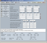
The calculation of the load capacity according to DIN 3990 Method B is also part of the module. The safeties for fatigue or limited life strength and static strength can be calculated. The calculation of surface durability (pitting), tooth bending strength and scuffing according the flash and integral temperature method is carried out. A diagram for the contact temperature over the length of the line of action is also available.
Alternatively, the load capacity calculation of the surface durability (pitting) and tooth bending strength according to ISO 6336 (2008) Method B is selectable. For the scuffing load capacity the ISO/TR 13989 is integrated.
There is a calculation of load spectra for cylindrical gears according to ISO 6336 Part 6. The determination is based on the Palmgren-Miner rule and the load-dependent K-factors are calculated for each torque class. The safeties are determined by way of iteration until the sum of damage parts is obtained. This method, demanded by the wind energy industry, is very accurate.
The materials and the lubricant can be comfortably selected from the database. Furthermore, other effects (grinding notches, mode of operation, etc.) can be taken into consideration.
The redo/undo function and the calculation report in HTML and PDF are also available in this module.

