

Web-based Calculation Software for Mechanical Engineering
___________________________________________
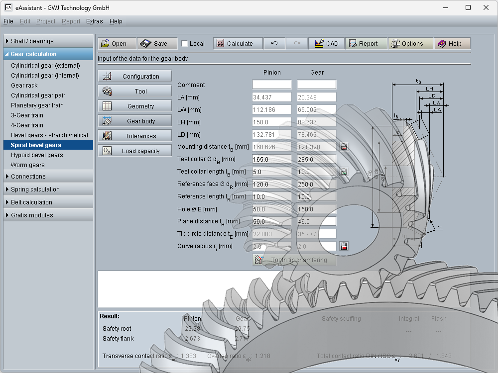
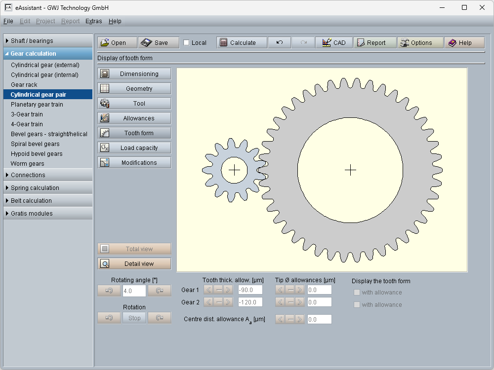
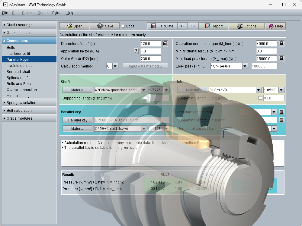
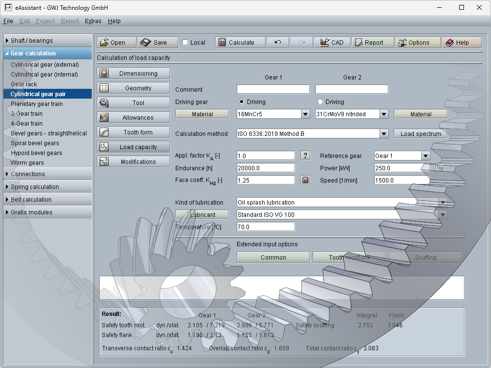
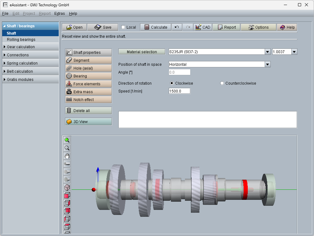
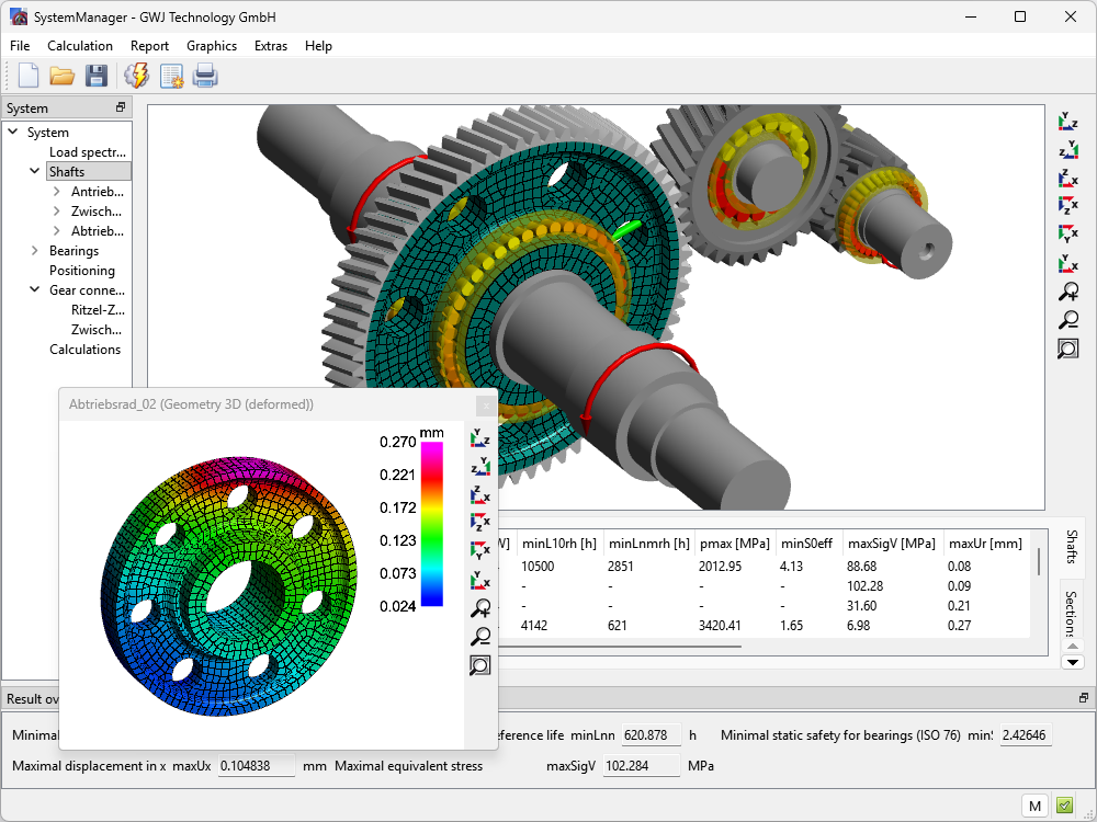
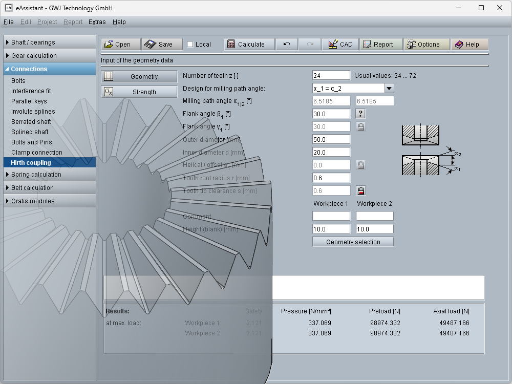
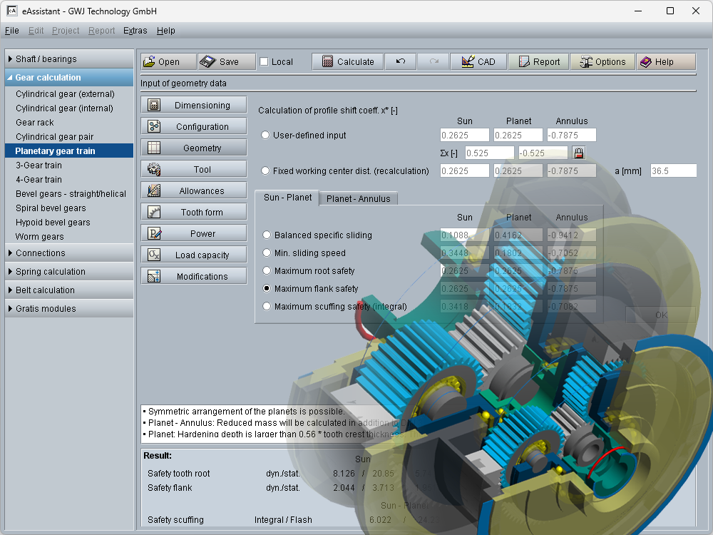
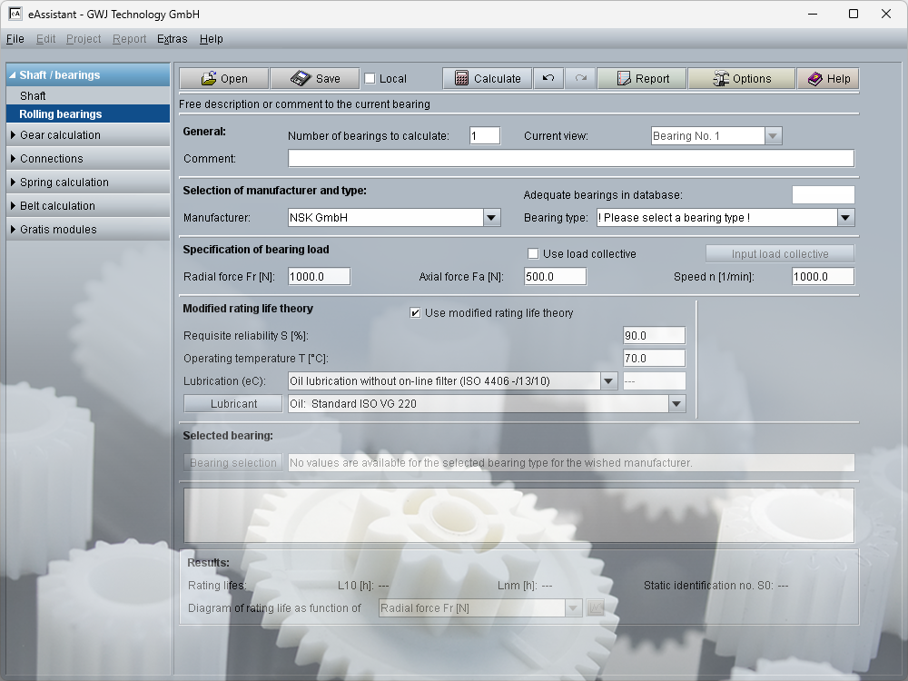
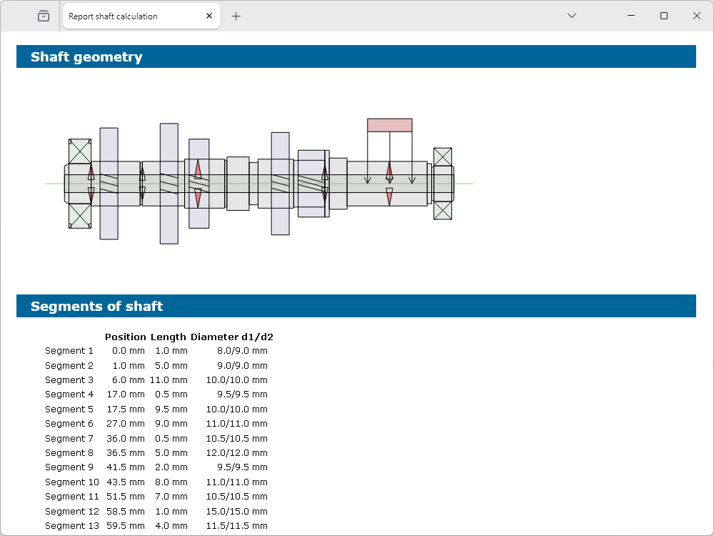
The eAssistant is your smart tool for precise engineering calculations: web-based, instantly ready, and efficient from the very first use. Based on recognized DIN, ISO, and VDI standards, it lets you quickly, safely, and practically calculate shafts, bearings, gears, and many other machine components. Automatic reports and intelligent CAD plugins ensure perfect documentation and seamless integration. Intuitive for beginners and powerful for professionals.
eAssistant – The Smarter Way to Calculate!