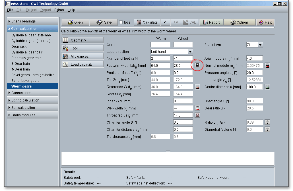
Please login with your username and your password. To start the calculation module for worm gears, please click the menu item ‘Gear calculation’ on the left side and then select ‘Worm gears’.

This module allows an easy and fast calculation of the geometry and load capacity of cylindrical
worm gear pairs with a globoid worm wheel. Worm gearsets are used to transmit power between
non-parallel, non-intersecting shafts, usually having a shaft angle of 90\(^\circ \). The gearset consists primarily
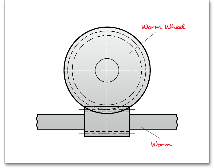
of two gear elements: the worm which is the driving gear in the shape of a screw and the worm
wheel, which is the driven gear in the shape of a common spur gear. Cylindrical worm gear pairs
have a cylindrical worm, whereas the worm wheel has a globoidal toothing. The most commonly
used type is the cylindrical worm. Worm drives have considerably more load-carrying capacity than
crossed-helical gearsets because the single enveloping worm gear drive has a line contact whereas the
crossed-helical has a point contact only. The result is an increased load capacity with smoother
and noiseless operation. Worm gear pairs are often used in power transmission and can reduce
rotational speed or transmit higher torque. The worm has a smaller diameter than the worm wheel.
The meshing action of worm and worm wheel is quite similar to that of gear racks and cylindrical
gears.
Worm gears have number of advantages over the other types of transmission:
The geometry calculation is based on DIN 3975. The calculation of the load capacity is according to DIN 3996
Method B, ISO/TR 14521 Method B and Niemann. The calculation module supports different flank forms. Profile
shift on the gear and tolerances can be taken into account.
All important calculation results will be calculated during every input and will be displayed in the result panel. A
recalculation occurs after every data input. Any changes that are made to the user interface take effect
immediately. Press the Enter key or move to the next input field to complete the input. Alternatively, use the Tab
key to jump from field to field or click the ‘Calculate’ button after every input. Your entries will be also confirmed
and the calculation results will displayed automatically. If the result exceeds certain values, the result will be
marked red.
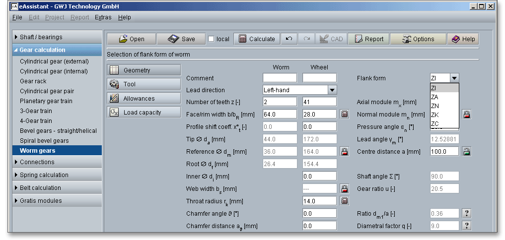
Cylindrical worms have various shapes of flanks depending on the tool and way of working. The flank forms are standardized in DIN 3975. ZA, ZK, ZN and ZI worms differ only slightly in load capacity, build-up of lubricating pressure, power loss or efficiency. The different profile forms can be selected from the listbox. ZI and ZK are the most common flank forms due to economical manufacturing with straight-sided grinding wheels.
The flanks are slightly convex and in transverse section they have an involute form, like cylindrical gears and
that is where the name comes from. The profile is produced by a trapezoidal-shaped lathe tool or by a
hob-cutter.
The profile of the ZA flank form has a trapezoidal form with straight-sided tooth profiles in the axial section. This
flank form is obtained by setting a lathe tool in such a way that its cutting edges lie in the axial
section.
The profile of the ZN flank is a trapezoidal form with straight sides in the normal section. The tooth profile is
slightly curved in the axial section. The form can be made by a lathe tool or a small trapezoidal milling
cutter.
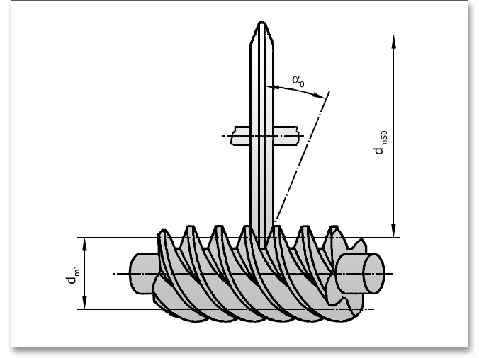
The tooth profile of the worm is convex in the axial section and is obtained by means of a disk-type rotary tool
having a trapezoidal profile. This is worked by a grinding wheel, whose axis is slewed to the worm axis by the
lead angle \(\gamma _{m}\). The profile crowning of the flanks depends on the tool diameter.
If you select this flank shape from the listbox, then there is an input option for the grinding wheel diameter \(d_{mS0}\) in the ‘Tool’ mask.
The flanks of this worm are concave in the axial section. It is worked with a grinding wheel, whose axis is slewed
to the worm axis by the lead angle \(\gamma _{m}\). The grinding wheel has a circular-arc profile with a radius
\(\varrho _{0}\).
A worm may be classified as right-handed or left-handed, depending on the direction of helix of the worm thread in which the thread winds around the root cylinder.
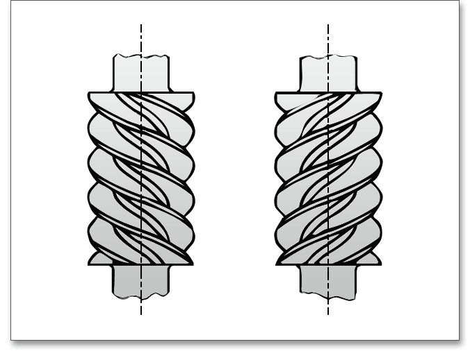
A worm is said to be right-handed if the tooth helix rises from left and goes up towards right. If the tooth helix goes towards, then it is a left-handed worm. Normally right-hand worms are used in preference to left-handed worms which are used in case of special requirements only. The flank direction of a worm gear set depends upon the direction of helix of the worm and the position of the worm wheel. A worm and worm wheel have the same hand of helix. A right-hand worm meshes with a right-hand wheel and a left-hand worm meshes with a left-hand worm wheel.

Wrapped around the central axis, the worms have one or more teeth in the form of screwed threads that rotate
the gears. The number of teeth \(z_{1}\) in the worm is the number of teeth as revealed by a transverse section. The
number of teeth is usually between 1 \(\le z_{1} \le \) 4.
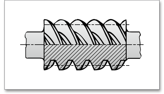
The calculations are based on the axial module and not on the normal module. The axial module \(m_{x}\) is the basic parameter of a worm and refers to the axial section of the worm or transverse section of the worm wheel. Axial section, normal section and transverse section are important parameters for the worm. The axial section is a section through the worm in a lengthwise direction that contains the axis of the worm. The transverse section is the section through a worm perpendicular to the axis of the worm. Normal section is the section through the worm that is perpendicular to the tooth at the pitch circle. The axial module of the worm \(m_{x}\) and the transverse module of the wheel \(m_{t}\) are the same when \(\Sigma \) = \(90^\circ \) (\(m_{x} = m_{t} = m\)). The meshing action of worm and worm wheel is quite similar to that of gear racks and cylindrical gears.
The calculation with the eAssistant software is possible with any modules including several decimal places. Click the label field for the axial module in order to enter and convert the diametral and circular pitch.
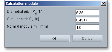
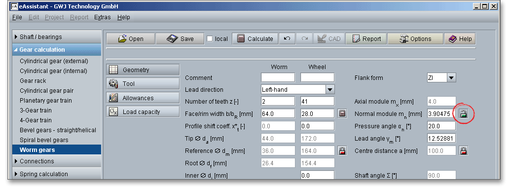
There is also the possibility to use the normal module \(m_{n}\) instead of the axial module. Activate the ‘Lock’ button to enable the input field for the normal module and add a value. Once you have clicked the ‘Lock’ button, the input field for the axial module will be disabled. Using the normal module affects the tip and root circle.
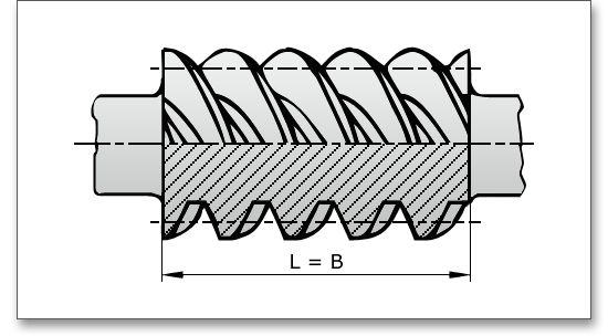
The facewidth or tooth length is the total width over the teeth measured in the direction of the axis of the worm.
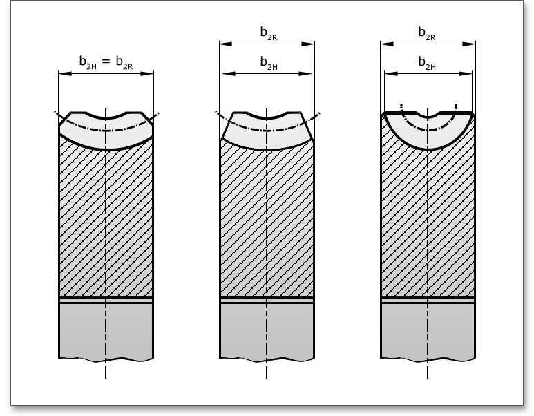
The following figure shows the dimensions of the worm. The value for \(b_{R}\) (\(b_{R} = b_{2R}\)) can be entered into the input field. \(b_{2H}\) and \(b_{2}\) are then determined.
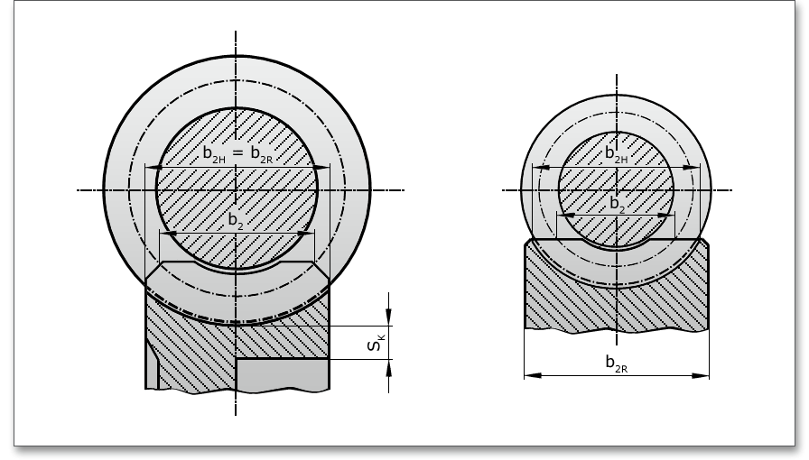
In order to optimize the worm, facewidth or the rim width of the worm wheel, click on the ‘Calculator’ button.
Profile shift is the radial distance between the reference cylinder of the worm and the reference circle of the
worm wheel. The profile shift is preferably \(x \geq 0\). Negative profile shift should be avoided. Since the
rack (axial section of worm) is not altered by profile shift, only the worm gear can have the profile
offset.
Recommendation for the profile shift coefficient (according to Niemann):
A pressure angle of \(\alpha _{n}\) = 20\(^\circ \) has been standardised for the general purpose applications and is most commonly
used. The default startup setting for the pressure angle is set to \(20^{\circ }\).
The lead angle \(\gamma _{m}\) is the acute angle between the tangent to a reference cylinder tooth trace and a transverse plane. The lead angle of the worm is equal to the helix angle of the worm wheel \((\gamma _{m} = \beta _{m})\).
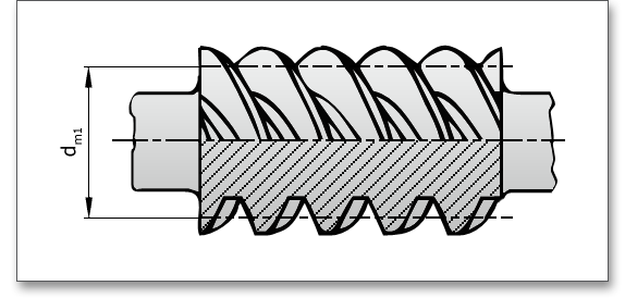
The main parameters are defined by means of the reference cylinder. Its diameter is the nominal worm diameter. The reference diameter can be freely chosen according to design requirements.
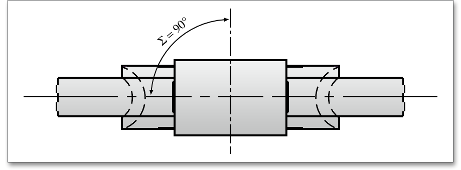
The centre distance \(a\) is the length of the line of centres between the axes of two gears. The shaft angle of a cylindrical worm gear pair is the acute angle between the worm and worm wheel axes. Worm gears are usually mounted on nonintersecting shafts which are set at a 90\(^\circ \) shaft angle. The shaft angle is usually 90\(^\circ \). Other shaft angles are not very often.
The web width can be considered here. There is the possibility to modify the web width by using the ‘Lock’ button. The ‘Lock’ button is still disabled. Enter the values for the inner or outer diameter into the input field. Then the ‘Lock’ button is enabled and the web width gets the same value as the rim width of the worm wheel.

The gear ratio \(u\) is the ratio of the number of teeth \(z_2\) in the worm wheel to the number of teeth \(z_{1}\) in the worm. The gear ratio shall be equal to the amount of the transmission ratio \(i = n_{1}/n_{2}\) as the ratio of speeds. The following number of teeth \(z_{1}\) in the worm can be used:
| \(i\) | 5...10 | 10...15 | 15...30 | > 30 |
| \(z_{1}\) | 4 | 3 | 2 | 1 |
| \(\gamma _{m}\) | to 15° | over 15°...25° | over 25°...35° | over 35° |
| \(\alpha _{n0} =\) | 20° | 22,5° | 25° | 30° |
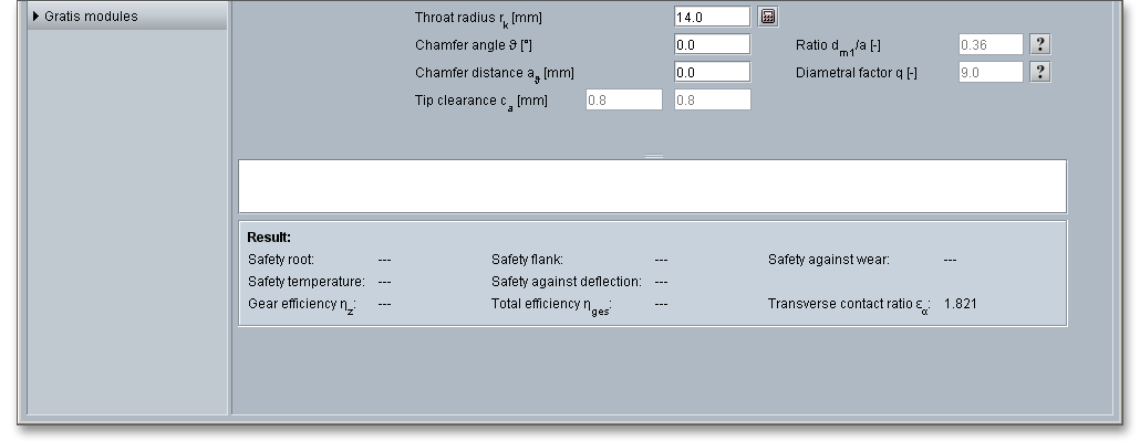
The throat radius \(r_{k}\) is the radius of the circle of generation of the throat.
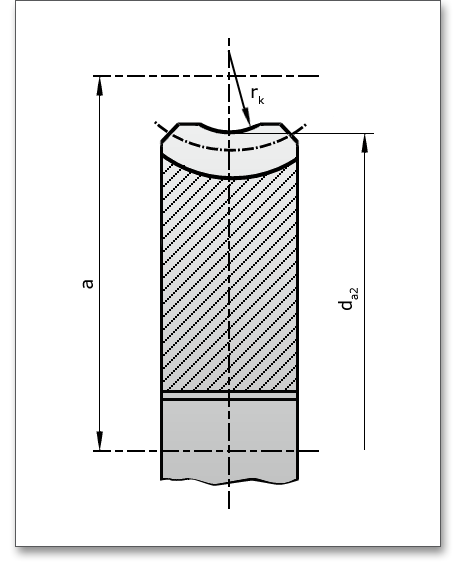
Here you get the possibility to dimension and optimize the throat radius of the worm wheel. In order to dimension the throat radius, click on the ‘Calculator’ button.

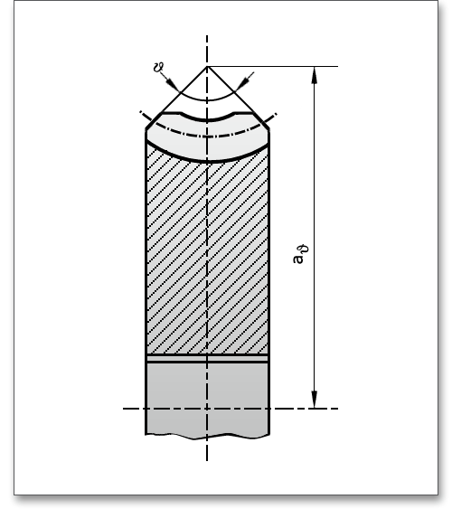
The chamfer angle is the angle between the elongated chamfers of the gear tooth. The chamfer distance is the distance from intersection point of the elongated chamfers to the worm axis. An individual input is also possible for both parameters.
The tip clearance of the worm is the distance between the worm tip diameter and the worm wheel root diameter. The tip clearance of the worm wheel is the distance between the worm wheel tip diameter and the worm root diameter.
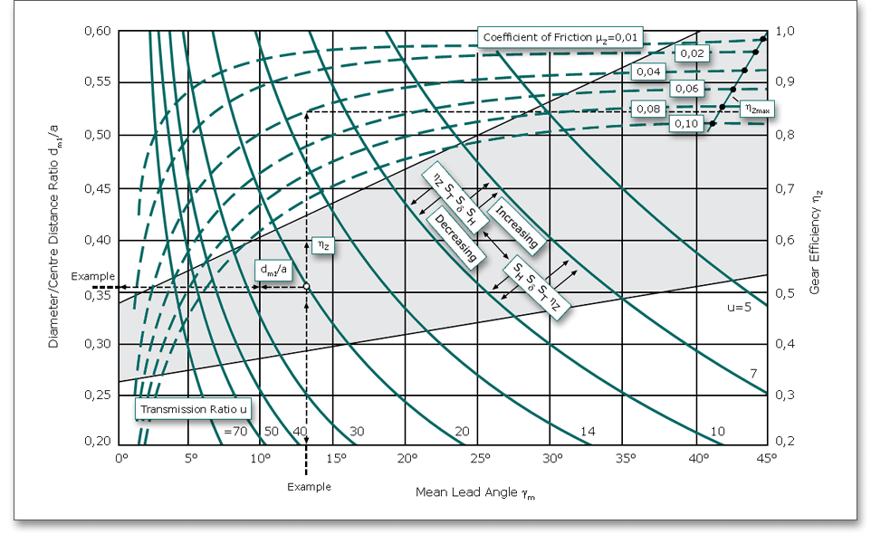
Click the ‘Question mark’ button to open the following figure to determine the diameter/centre distance ratio \(d_{m1}/a\). With increasing \(d_{m1}/a\), the safety factors against pitting and deflection also increase but the gear efficiency and the temperature safety decrease. For higher efficiency, a smaller diameter/centre distance ratio \(d_{m1}/a\) has to be used but the deflection must be considered (risk of meshig interferences).
The form factor \(q\) is the ratio between the worm reference diameter and the axial module. This is an important parameter of the worm as it determines the shape of the worm and as a consequence also determines the moment of resistance of the worm against bending. In practice \(q\) lies between 6 and 17. For normal design, an average value of \(q\) = 10 can be taken. With a smaller form factor, \(\gamma _{m}\) increases but the worm becomes thinner. With a larger value, \(\gamma _{m}\) becomes smaller but also stronger. There is a ‘Question mark’ button next to the field for the form factor. Click this button to get some additional information. The figure shows how the form factor affects the shape of the worm.

Worm wheel teeth can be produced by hobbing. The tool is essentially a duplicate of the mating worm in size and thread design. That means that the worm wheel may not be paired with other worms. The flank forms ZA, ZN and ZK can be cut on a lathe (single-part production). Side milling cutters or cutting wheels (peeling) are applied in small-batch production. Multi-threaded worms can be produced on hobbing machines. Small worms may be finished by rolling. Precise worms may be finished by grinding, profile grinding is preferred due to higher efficiency.
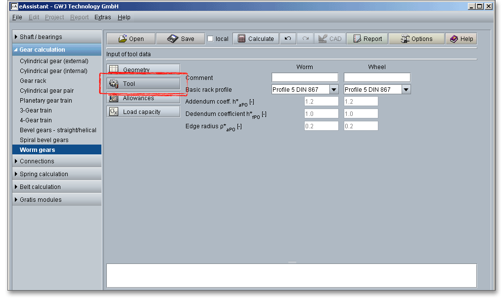
Please note: If you want to add some own notes, comments or a description for worm and worm wheel, then
use the comment line.
The following standard basic rack tooth profiles are available for your calculation. Choose your profile from the listbox:
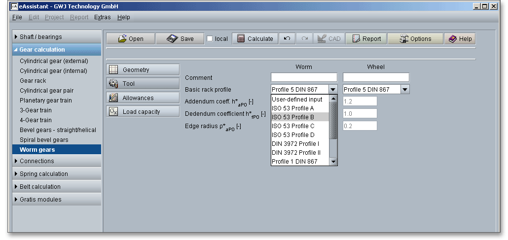
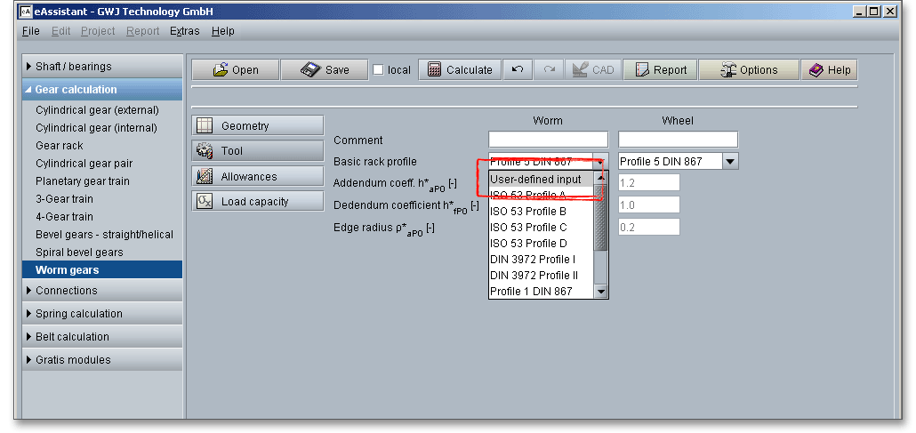
If you select ‘User-desined input’, then the input fields for the addendum coefficient, the dedendum coefficient and the edge radius are activated. Now you can modify the basic rack profile.
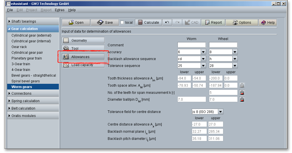
A manufacturing of workpieces with accurate nominal dimensions is impossible. Like cylindrical gears, some backlash must be allowed to prevent gears from jamming. For smooth rotation and correct operation of worm and worm wheel, backlash or play is necessary. Generally speaking, worm gears require more backlash than do spur or helical gears. Quite often a steel worm and bronze gear are housed in a cast-iron casting. The temperature of the gearset may change quite considerably during operation because of the high sliding velocity of the worm threads. Diffential expansions can easily cause an appreciable change in backlash.
The choice of the right toothing quality is determined by economical aspects depending upon the intended purpose and manufacturing process. In all fields of gearing, the control of gear accuracy is essential. Several classes or grades of accuracy can be set. 12 grades (12 to 1) are defined according to DIN standards. Accuracy grade ‘1’ describes the highest possible accuracy, ‘12’ a very low accuracy. Very fine accuracies are relatively difficult to manufacture.
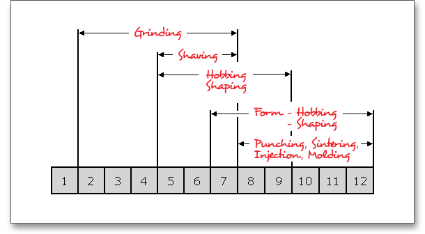
Select the appropriate quality between 1 and 12 by using the following listbox.

The following table provides some reference values for the selection of the quality of worm gears according to Niemann:
| Recommendation for the Selection of Accuracy of Worm Gear Drives1
| ||
| Accuracy | Field of Application | |
| Worm\(^a\), Worm Wheel\(^a\) and Housing\(^b\) | Centre Distance\(^c\) | |
| 4 ... 5 | 6\(^d\) | Sub-transmissions for machine tools, controls, straighteners (wobble needs to be minimzed in particular), gearboxes for extreme running smoothness with \(v_{m1} > 5 m/s\) |
| 5 ... 6 | 7\(^d\) | Elevators, slewing drives, smooth-running power gears with \(v_{m1} > 5 m/s\) |
| 8 ... 9 | 8\(^d\) | Industrial gears without special requirements on running smoothness, \(v_{m} < 10 m/s\) |
| Worms mostly case-hardened or surface hardened, ground, maybe polished; worm wheels
hobbed and run-in
| ||
| 10 ... 12 | 10\(^d\) | Auxiliary drives, manual drives, actuating gears \(v_{m1} \le 3 m/s\) |
| \(^a\)According DIN 3961 to 3963; profile deviations on gear wheel are less critical; tooth flanks run-in.
Single normal pitch, total pitch as well as run-out deviations can be easily maintained.
| ||
| \(^b\)Parallel axes according to DIN 3964
| ||
| \(^c\)According to DIN 3964
| ||
| \(^d\)For single and double enveloping worms, one accuracy grade finer for multiple-threaded worms
| ||
| 1 from: Niemann, G.: Maschinenelemente, Volume 3, Schraubrad-, Kegelrad-, Schnecken-, Ketten-,
Riemen-, Reibradgetriebe, Kupplungen, Bremsen, Freilaeufe, 1986, p. 98, table 25/6
| ||
Please note: For high-loaded worm gearsets with hardened and ground steel worm and milled worm wheel
made of material which shows good running-in behaviour, the accuracy grade of the worm should be
one accuracy grade better than the worm wheel. The effect of the running-in process normally
improves the quality. Accuracy grade 8 could be selected for the worm, accuracy grade 9 for the worm
wheel.
The system for gearings is very similar to the DIN system of fits and tolerances. For the system of fits for gear transmissions letters are used to indicate the deviation from basic (nominal) size, a number defines the width. There are clearance fits for gearings, therefore, lower case characters ‘h’ to ‘a’ appear. The tolerances of worm gearsets follow DIN 3974. The tolerancy system is largeley based on DIN 3961 for cylindrical gear teeth. If you select the entry ‘user defined input’, the input field for the tooth thickness allowances is enabled and you can define your individual values.

One of the most important criteria of gear quality is the specification and control of tooth thickness. The magnitude of tooth thickness and its tolerance is a direct measure of backlash when the gear is assembled with its mate. Dimensional changes, due to thermal expansion, do not allow a zero-backlash assembly. The tooth thickness allowance has to be determined that no jamming occurs. To prevent that jamming of gears during the operation, it is necessary to decrease tooth thickness by a minimum amount (\(A_{sne}\) and \(A_{sn}\)). \(A_{sn}\) is always negative.
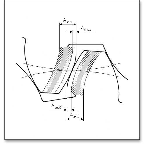
The tooth space allowance \(A_{W}\) is the difference between the actual dimension and the nominal dimension of the span measurement \(W{_k}\). The actual measurement of the span measurement gets smaller for external gears by negative allowances for a zero-backlash assembly. The upper and lower tooth space allowance are displayed as well. For an own input of the tooth thickness allowances, the tooth space allowances can be defined as well. The ‘Lock’ button next to the input field of the tooth space allowances is enabled. Therefore, you can change the tooth space allowances.

The three-wire method is used to check the worm gearset. It is a very accurate method but also very complex.
Based on the traditional three-wire method of measuring screw threads, G. Bock has developed a
calculation method that allows to use the three-wire measurement for all flank forms of a worm in
order to determine the tooth thickness. In the three-wire method, three wires of equal diameter are
placed in the thread; two on one side and one on the opposite side. When the micrometer is in
contact with all three wires, this insures measuring perpendicular to the axis of the screw thread.
eAssistant uses the method according to G. Bock (Bock G., Noch R., Steiner O.: Zahndickenmessung an
Getriebeschnecken nach der Dreidrahtmethode. Physikalisch-Technische Bundesanstalt, Braunschweig,
1974).
The calculation program determines the number of teeth for the span measurement of the worm wheel (number of teeth across the span measurement has to be gauged). By using the ‘Lock’ button you are able to activate the input field and you can enter your own input value. If you click the button again, the previous input value appears. The ball/pin diameter is also automatically set. Click the ‘Lock’ button to enable the input field and enter your own input value. If you disable the button again, the previous input value appears.

To ensure smooth and continuous operation and to prevent gears from jamming together, a play is necessary
between the mating pair of gear teeth. The center distance and the gear fits have an important influence on the
backlash. The gear fit selection defines the tolerances of the centre distance with the backlash. The gear fit
selection provides only one tolerance field. The allowances are indicated for the ‘JS’ field. These conform to the
ISO basic tolerances. The backlash is dependent upon the tooth thickness allowances, the tooth space
allowances and the centre distance. Hence, if you change the centre distance, then the backlash is changed,
too.
Select the option ‘User-defined’ from the listbox. Now you are able to enter your own centre distance
allowances. Confirm your entries with the Enter key. The backlashes are automatically determined.
The centre distance allowance \(A_{a}\) is the allowed deviation of the centre distance \(a\) from the nominal centre distance. The allowances are indicated with \(\pm \) to get no improper major allowances from the nominal centre distances with gears having several axes.
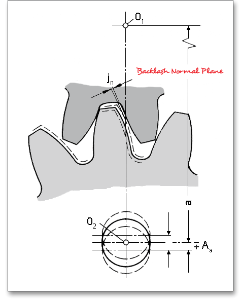
The general purpose of backlash, a clearance between mating gear teeth, is to prevent gears from jamming due to thermal expansion of the housing and gears and to avoid manufacturing errors and mounting inaccuracies. Like cylindrical gears, some backlash must be allowed for worm gearsets.
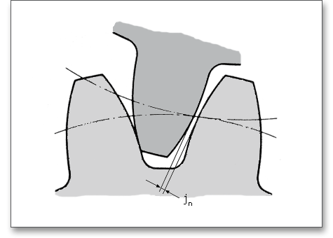
Worm gears require more backlash than do spur or helical gears because the steel worm and bronze gear are
housed in a cast-iron casting. The temperature of the gearing changes during operation because of the high
sliding velocities, the material expands and causes an appreciable change in backlash. The normal backlash \(j_{n}\) is
the minimum distance between each meshed tooth flank in a pair of gears, when it is set so the tooth surfaces
are in contact.
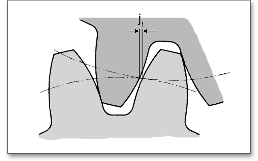
The backlash pitch diameter is the length of arc on the pitch circle. The length is the distance the gear is rotated until the meshed tooth flank makes contacts while the other mating gear is held stationary.
The load capacity of worm gearings is mainly influenced by the material pairing. In addition, heat caused by friction on flank may cause thermal damage and has to be taken into account. The calculation of the load capacity is based on DIN 3996 Method B, ISO/TR 14521 Method B and Niemann. The calculations according to DIN and ISO are similar.
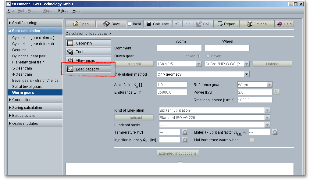
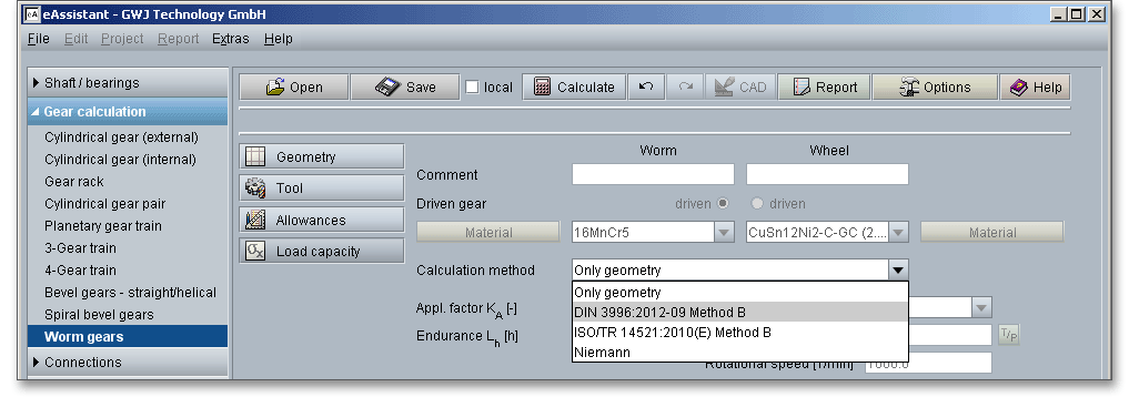
Click on the ‘Load capacity’ button to get to the calculation mask. You will notice that all input fields or listboxes are disabled. When you select the entry ‘DIN 39960 Method B’ or ‘ISO/TR 14521 Method B’ or ‘Niemann’ from the listbox ‘Calculation method’, all input fields are enabled. In case you do not need the calculation for load capacity, the calculation can be disabled. Thus, the size of the calculation report becomes smaller. The following conditions can limit the rated load capacity:
The extended input options allow to add additional entries, for example the permissible deterioration of quality or the bearing spacing of the worm shaft.
You can add a description or a short comment to worm and wheel. The notes will appear later in the calculation report.

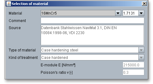
The worm gearing has a high sliding component in its tooth meshing action. Therefore, the material selection plays an important role. Good sliding properties, wear resistance and good thermal conductivity are required. The material pair should show a good running-in behaviour, so that the sliding surfaces adapt quickly without scuffing damage and compensate for tooth errors and deformations. Worms and worm wheels are, therefore, often made out of two different materials. Worms are made of case-hardened or nidrided steels. The basic material for the worm wheel is bronze (CuSn). Select an appropriate material directly from the listbox or click on the button ‘Material’ to open the material database.

The material database provides some detailed information on the several kinds of material. If the listbox is active, the two arrow keys ‘Up’ and ‘Down’ of your keyboard allows you to search through the database, so you can compare the different values with each other.
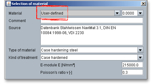
Please Note: In case there is no material that will fulfill the design requirements, then simply define your individual material. Select the option ‘User defined input’ and all inputs and options are activated and you can specify your individual material very easily. Your inputs will be saved to the calculation file. Please be advised that changing the material will delete your defined inputs and you have to enter the inputs again.
The application factor \(K_{A}\) evaluates the external dynamic forces that affect the gearing. These additional forces are largely dependent on the characteristics of the driving and driven machines as well as the masses and stiffness of the system, including shafts and couplings used in service.
| Application Factors \(K_{A}\) According to DIN 3990-1: 1987-122
| ||||
| Working Characteristics | Working Characteristics of the Driven Machine | |||
| of the Driving Machine | Uniform | Light shocks | Moderate shocks | Heavy shocks |
| Uniform | 1.0 | 1.25 | 1.5 | 1.75 |
| Light shocks | 1.1 | 1.35 | 1.6 | 1.85 |
| Moderate shocks | 1.25 | 1.5 | 1.75 | 2.0 |
| Heavy shocks | 1.5 | 1.75 | 2.0 | 2.25 or higher |
| 2 from: DIN 3990 Part 1, December 1987, p. 55, table: A1
| ||||
The inputs for the power, speed and torque apply for the appropriate gear that is selected in the listbox. For the
other gear, speed and torque are determined from the reference gear.
The power, torque and speed are dependent upon each other. Click on the adjacent button ‘T/P’ to switch
between the input for the torque and the input for the power. If you click on the ‘TP’ button, then you can enter
either the torque or the power. The values are converted. The description of the input field changes accordingly
into ‘Torque’ or ‘Power’.
Worm gearsets operate under difficult conditions, presenting unique lubrication demands, so care should be taken for lubrication. The right choice of the lubricant is a decisive factor for the operating safety and life expectancy. In case of lubrication, the following factors must be considered:

Grease lubrication can be used for worm gear units that are open, so long as it runs at low speed. Splash
lubrication is used with an enclosed system. Depending on the speed, the following methods of lubrication can
be used (reference values acc. Decker: Maschinenelemente, p. 553):
1. Worm immersed
2. Only worm wheel immersed

For injection lubrication, the worm may be above or below the worm wheel, also at side. For splash lubrication,
the worm is placed as low as possible depending on the circumferential velocity, with \(\nu _{1} \le \) 1 m/s also at side, for \(\nu _{1} \le \) 5
m/s also above.
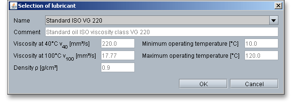
Click on the ‘Lubricant’ button and open the lubricant database. The extensive database contains the lubricants including all detailed information on oils and greases, for example density, viscosity or operating temperatures.
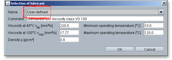
Select ‘User-defined’ from the listbox to input your individual lubricant data.
The types of oils most commonly used to lubricate worm gears are EP mineral gear oils and synthetics. Mineral oils simplify the running-in process and help to reduce the risk of scoring. Two major types of synthetic gear oils have been used successfully: polyalphaolefins and polyalkelene glycols. Synthetic gear oils based on polyalphaolefin or polyglycol show a considerably lower gear friction coefficient and lead to a further efficiency increase. Synthetic gear oils offer higher operating temperature and reduce abrasive wear.

The material-lubricant factor \(W_{ML}\) takes into account the influence of the combined effects of the wheel material and lubricant to the wear behaviour. If other materials or lubricants are used, tests should be run, if possible, in order to estimate the effects.
| Material-Lubricant Factor \(W_{ML}\)3
| ||||
| Worm: 16MnCr5 acc. DIN EN 10084 | Material-Lubricant Factor \(W_{ML}\) | |||
| Worm wheel material | acc. | Mineral oil | Polyalphaolefin | Polyglycol |
| CuSn12-C-GZ | 1,6\(^{1)}\) | 1,6\(^{1)}\) | 2,25\(^{2)}\) | |
| CuSn12Ni2-C-GZ | 1,0\(^{1)}\) | 1,0\(^{1)}\) | 1,75\(^{2)}\) | |
| CuSn12Ni2-C-GC | DIN EN 1982 | 4,1\(^{2)}\) | 4,1\(^{2)}\) | 4,1\(^{2)}\) |
| CuAl10Fe5Ni5-C-GZ | 1 | 1 | -\(^{3)}\) |
|
| EN-GJS-400-15 | DIN EN 1563 | 1\(^{1)}\) | 1\(^{1)}\) | 1\(^{1)}\) |
| EN-GJL-250 | DIN EN 1561 | 1\(^{1)}\) | 1\(^{1)}\) | 1\(^{1)}\) |
| 1) Scatter zone \(\pm \) 25\(\%\)
| ||||
| 2) Scatter zone \(\pm \) 30\(\%\)
| ||||
| 3) No values are available and risk of scuffing exists.
| ||||
| 3 from: DIN 3996, September 2012, p. 38, tab.: 6
| ||||
The value for the material-lubricant factor can be individually modified. Click the ‘Lock’ button to enable the input field and enter your own value. If you click the button again, the previous input value appears.

Click the button ‘Extended input options’ to add additional entries, for example the permissible deterioration of quality, ambient temperature or inputs for the bearing. The extended input options may vary depending on the selected calculation method (DIN, ISO, Niemann).
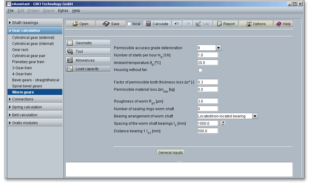
The worm wheel teeth can be plastically deformed or broken as a result of a too high tooth root stress. The
accuracy of the worm wheel is deteriorated due to plastic deformations and wear. DIN 3996 recommends that
the manufacturer experience must be considered for worm wheel qualities better than accuracy grade 7. If the
accuracy grade deterioration is accepted, higher values are allowed according to DIN 3996. The input field
shows the accuracy previously selected in the main mask ‘Allowances’. The permissible accuracy grade
deterioration must not fall below this value.
A distinction is made between gear units with and without fans. If a fan is used, the heat dissipation
changes. For smaller gearboxes, the heat transfer coefficient for gears with fans is up to 30% higher
than for gearboxes without fans. The coefficient may increase further with increase in worm speed
and centre distance. The heat transfer coefficient depends on the gearbox design and the worm
speed.
\(\Delta \)s is the tooth root thickness loss through wear during the required life expectancy. The tooth thickness is required for the calculation of the wear safety and is taken into account when calculating the root safety.
Wear occurs through material removal caused by sliding velocity, operating temperature, type of lubricant etc.
The lubricant becomes contaminated with abrasive particles and the lubricating capability is reduced. The
permissible material loss \(\Delta m_{lim}\) can be defined (dependant on oil change intervals, oil quantity and bearing
lubrication).
Niemann provides some reference values for the roughness of the worm:
Ground \(R_{z} \le \) 3...4 \(\mu \)m for m \(\le \) 8, \(R_{z} \le \) 8 \(\mu \)m for m > 8
Milled \(R_{z} \le \) 12,5 \(\mu \)m for m \(\le \) 8, \(R_{z} \le \) 25 \(\mu \)m for m > 8
Sealing rings prevent oil from escaping and offer adequate protection against contamination. This number is
needed for the calculation of the sealing power loss. The power loss at the seals on the worm wheel shaft can
be neglected.
Adjusted bearing arrangements, for example separable ball bearings, angular contact ball bearings and tapered
roller bearings, are suitable for small to medium-sized dimensions. Located/non-located bearings, for example
double-row angular contact ball bearings, can be considered for large and heavily-loaded worm gear
units.
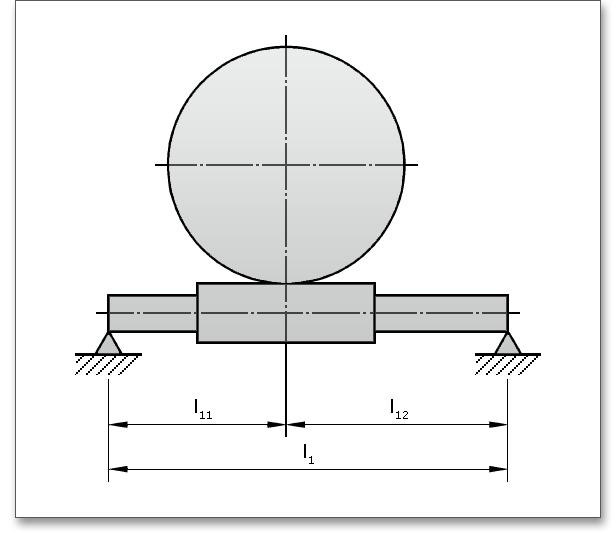
The bearing spacing for the worm shaft should be small in order to keep the deflection under load low.
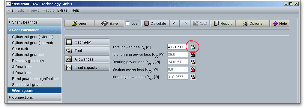
Click the button ‘Power loss’ and the software displays directly the power loss. If required, the power loss can be individually modified by using the ‘Lock’ button.
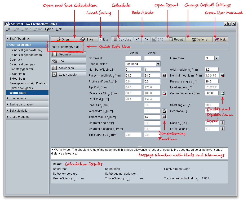
The calculation module provides a message window. This message window displays detailed information, helpful hints or warnings about problems. One of the main benefits of the program is that the software provides suggestions for correcting errors during the data input. If you check the message window carefully for any errors or warnings and follow the hints, you are able to find a solution to quickly resolve calculation problems.

The quick info tooltip provides additional information about all input fields and buttons. Move the mouse pointer over the input field or button, then you will get the additional information. This information will be displayed in the quick info line.

All results will be calculated during every input and will be displayed in the result panel. A recalculation occurs after every data input. Any changes that are made to the user interface take effect immediately. In case a minimum safety is not fulfilled, the result will be marked red. Press the Enter key or move to the next input field to complete the input. Alternatively, use the Tab key to jump from field to field or click the ‘Calculate’ button after every input. Your entries will be also confirmed and the calculation results will displayed automatically.

After the completion of your calculation, you can create a calculation report. Click on the ‘Report’ button.

The calculation report contains a table of contents. You can navigate through the report via the table of contents that provides links to the input values, results and figures. The report is available in HTML and PDF format. Calculation reports, saved in HTML format, can be opened in a web browser or in Word for Windows.
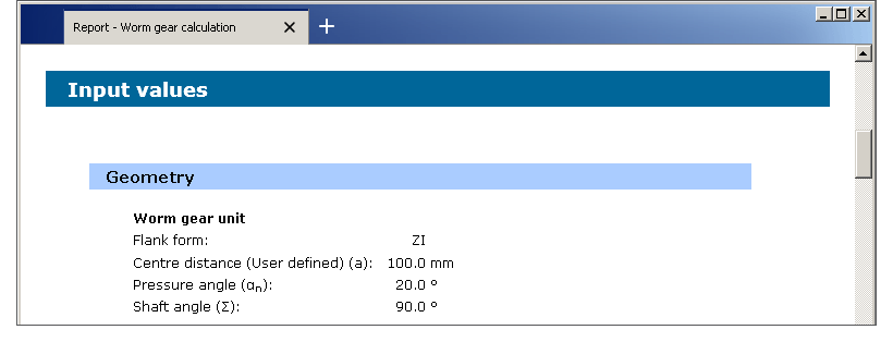
You may also print or save the calculation report:
If you click on the symbol ‘Print’, then you can print the report very easily.
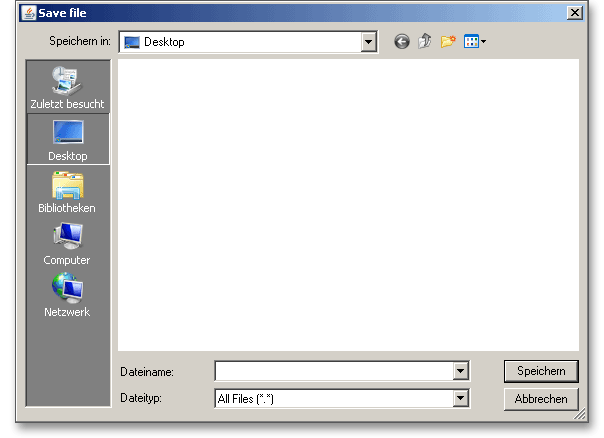
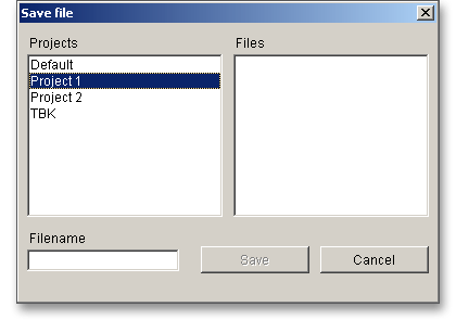
When the calculation is finished, it is easy to save the calculation. You can save your calculation either to the eAssistant server or to your computer. Click on the button ‘Save’.

Before you can save the calculation to your computer, you need to activate the checkbox Local’ in the calculation module. A standard Windows dialog for saving files will appear. Now you will be able to save the calculation to your computer.
In case you do not activate the option in order to save your files locally, then a new window is opened and you can save the calculation to the eAssistant server. Please enter a name into the input field ‘Filename’ and click on the button ‘Save’.
The ‘Undo’ button allows you to reset your inputs to an older state. The ‘Redo’ button reverses the undo.

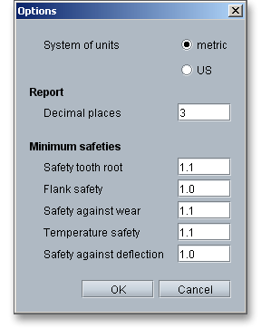
Click on the button ‘Options’ in the top menu bar to change some general settings.

This option allows you to change the following general settings:
