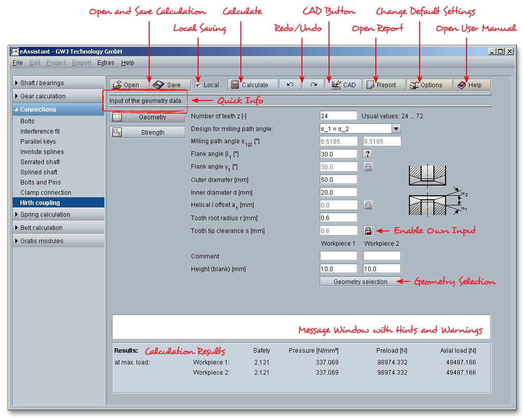
Please login with your username and your password. To start the calculation module for Hirth couplings, please click the menu item ‘Connections’ on the left side and then select ‘Hirth coupling’.
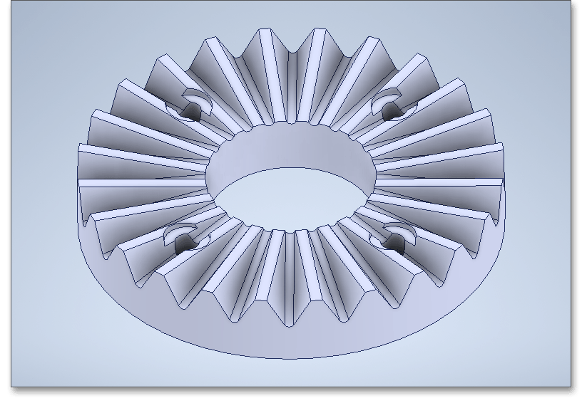
The Hirth coupling (or face spline) with its straight, triangular teeth, belongs to the shaft-hub connections. This form-locking, self-centering and easily detachable connection component connects shafts, disks, rotors, wheels and cranks with remarkable precision and maximum torque capacity. The Hirth coupling offers a number of significant advantages: Hirth teeth are very robust and suitable when changing forces and it requires only minimal installation space due to the small size. Assembly and disassembly are quick and easy. During assembly, the components are self-centering. The high degree of repeat accuracy allows disassembly and reassembly. Thanks to modern machine tools and manufacturing processes, the coupling can also be produced cost-effectively. Grinding and milling are used for this.
A Hirth coupling is designed as follows: radial teeth are milled into the end faces of each of the two parts to be
connected, the threaded bolt presses the parts together. Tooth flanks, tooth apex and tooth roots intersect in the
center of the shaft to be coupled. Due to the tapered shape of the radially positioned teeth, a centering effect
occurs during assembling.
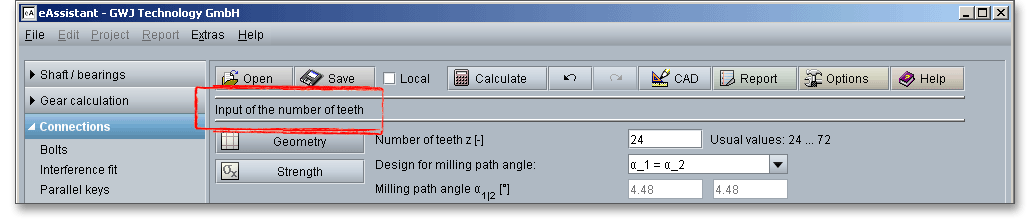
With the input of the number of teeth, outer and inner diameter, flank angle and tooth root radius, the eAssistant module calculates the geometry of the Hirth coupling.
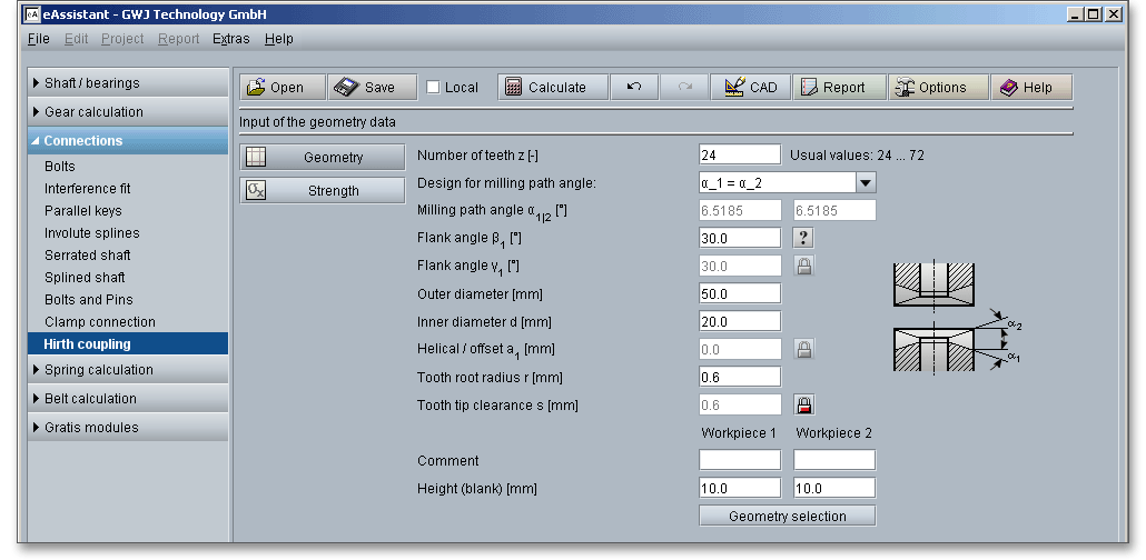
Several factors are usually decisive when selecting the number of teeth: installation space, application, material, load as well as the the torque to be transmitted. Depending on outer diameter, 12, 24, 36, 48 72 or 96 teeth are milled (in special cases also 144 or 192 teeth) and, if required, then ground. In case of doubt, the higher number of teeth is preferred. There are some recommended values for the selection of the number of teeth:
| Outer Diameter | Number of Teeth |
| up to 30 mm | 12 teeth |
| from 30 to 60 mm | 24 or 36 teeth |
| from 60 to 120 mm | 36 or 48 teeth |
| over 120 mm | 72 or 96 teeth |
The milling path angle \(\alpha \) is the angle between milling path and a plane perpendicular to the workpiece axis. Three different designs can be selected from the listbox:
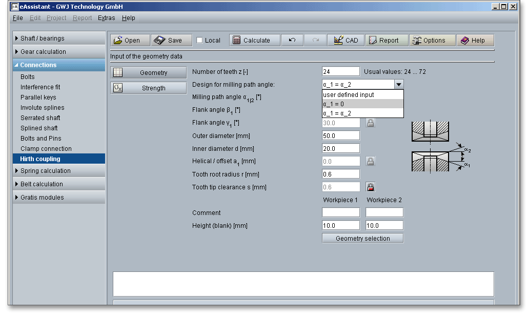
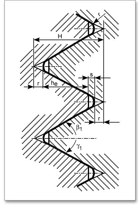
\(\beta \)and \(\gamma \) are the flank angles of the teeth, measured in a plane perpendicular to the milling direction. The tool must have these angles (cutter, planing knife). In most cases, the teeth are designed with the same flank angles on both sides but there are also cases where the teeth are given different flank angles on both sides. The following figure shows the tooth profile that is created when the outer diameter of a Hirth coupling is developed.
A Hirth coupling can be designed with straight or helical teeth. The module currently only allows the calculation
of straight Hirth couplings.
A radius is provided in the tooth root area, which for manufacturing reasons must be constant over the entire length of the tooth root edge. There is a flattening at the tooth tip, the width is also constant along the entire tooth tip. Here are some recommendations for the tooth root radius \(r\) as well as the tooth tip clearance \(s\).
| Tooth Root Radius \(r\)[mm] | 0,3 | 0,6 | 0,9 |
|
| Tooth Tip Clearance \(s\)[mm] | 0,4 | 0,6 | 0,9 |
|
There is the possibility to enable the input field for the tooth tip clearance by using the ‘Lock’ button. Now you can enter your own value for the tooth tip clearance. If you click the button again, the previous input value appears and the input field is disabled again.
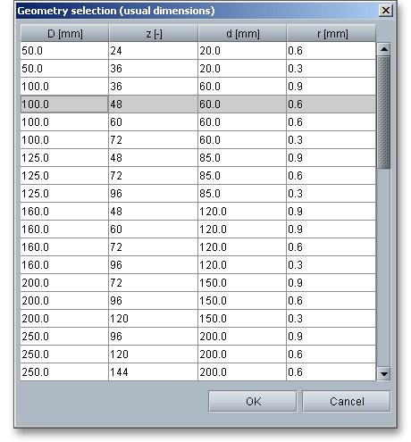
Click the button ‘Geometry Selection’ to select usual dimensions for Hirth couplings from the integrated database. Here, diameters from 50 to 900 mm can be chosen – each with a suitable number of teeth, inner diameter and tooth root radius.
The permissible pressures of the Hirth coupling are determined from material properties analog to DIN 6892 for parallel key connections.
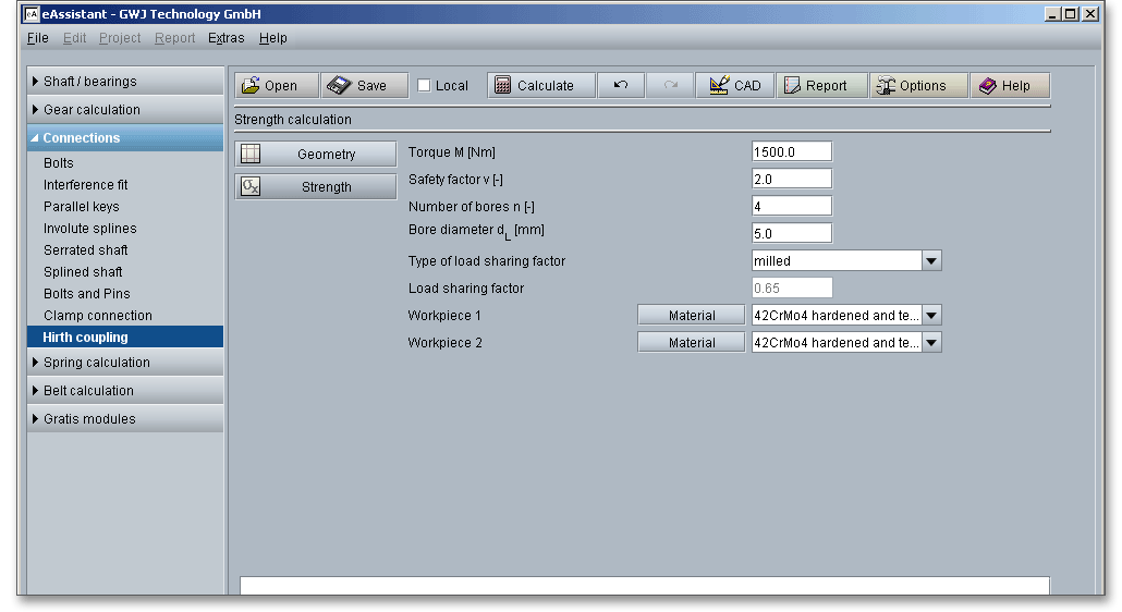
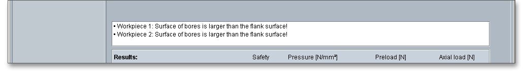
A number of bores and as well as a bore diameter can be added to the Hirth coupling. These reduce the flank area available for torque transmission.
As a result of manufacturing deviations, the flank surface pressure is not evenly distributed over all teeth (i.e. over the circumference). This is taken into account by the load sharing factor. While a load sharing factor of up to approx. 65% can be achieved in the milled design, a load sharing factor of up to 75% is achieved with the ground design. This increases not only the accuracy, but also the transmittable torque.
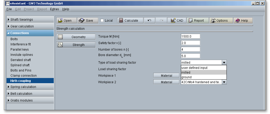
Select the option ‘User-defined input’ from the listbox to enter your own value for the load sharing factor. Confirm with the Enter key.
Select the material directly from the listbox or click on the button ‘Material’ to open the material database.
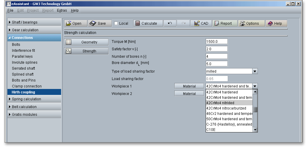
You will get detailed information on the material. The two cursor keys ‘Up’ and ‘Down’ of your keyboard allows you to navigate through the material database, so you can compare the different material properties with each other.
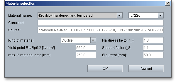
In case there is no material that will fulfill the design requirements, then simply define your individual material. Select the option ‘User defined’.
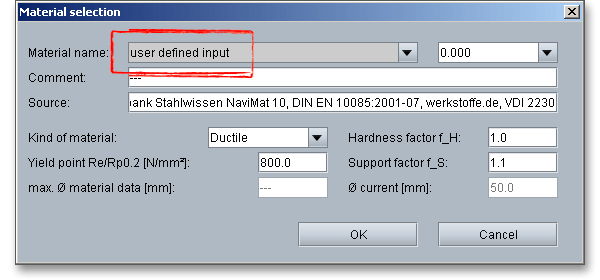
All inputs and options are enabled and you can specify your individual material very easily. Enter, for example,
kind of material, yield point, support factor or hardness factor. Click the button ‘OK’ to confirm the
values.
The calculation module provides a message window. This message window displays detailed information, helpful hints or warnings about problems. One of the main benefits of the program is that the software provides suggestions for correcting errors during the data input. If you check the message window carefully for any errors or warnings and follow the hints, you are able to find a solution to quickly resolve calculation problems.
The quick info tooltip provides additional information about all input fields and buttons. Move the mouse pointer over the input field or button, then you will get the additional information. This information will be displayed in the quick info line.
The inclination of the tooth flanks results in an axial load. When compressed together, the teeth support each other if the preload is sufficient. The calculation results for safety, axial load, pressure, and preload are already calculated during every input and are displayed in the result panel.
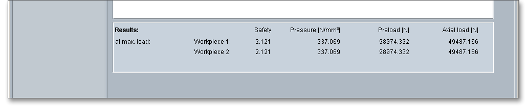
All results will be calculated during every input and will be displayed in the result panel. A recalculation occurs
after every data input. Any changes that are made to the user interface take effect immediately. In case a
minimum safety is not fulfilled, the result will be marked red. Press the Enter key or move to the next input field
to complete the input. Alternatively, use the Tab key to jump from field to field or click the ‘Calculate’
button after every input. Your entries will be also confirmed and the calculation results will displayed
automatically.
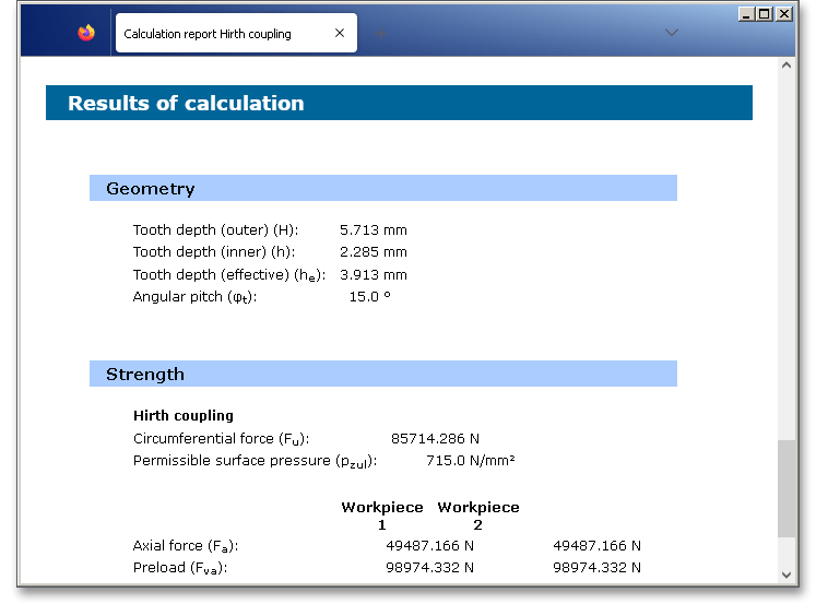
After the completion of your calculation, you can create a calculation report. Click on the ‘Report’ button.
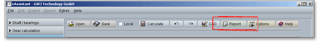
The calculation report contains a table of contents. You can navigate through the report via the table of contents that provides links to the input values, results and figures. The report is available in HTML and PDF format. Calculation reports, saved in HTML format, can be opened in a web browser or in Word for Windows. You may also print or save the calculation report:
When the calculation is finished, it is easy to save the calculation. You can save your calculation either to the eAssistant server or to your computer. Click on the button ‘Save’.
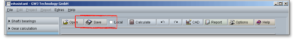
Before you can save the calculation to your computer, you need to activate the checkbox Local’ in the calculation module.
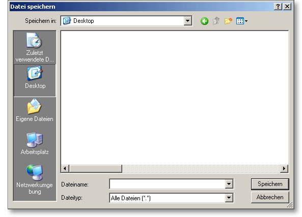
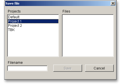
In case you do not activate the option in order to save your files locally, then a new window is opened and you can save the calculation to the eAssistant server in your eAssistant account. Please enter a name into the input field ‘Filename’ and click on the button ‘Save’.
The ‘Undo’ button allows you to reset your inputs to an older state. The ‘Redo’ button reverses the undo.
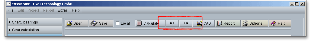
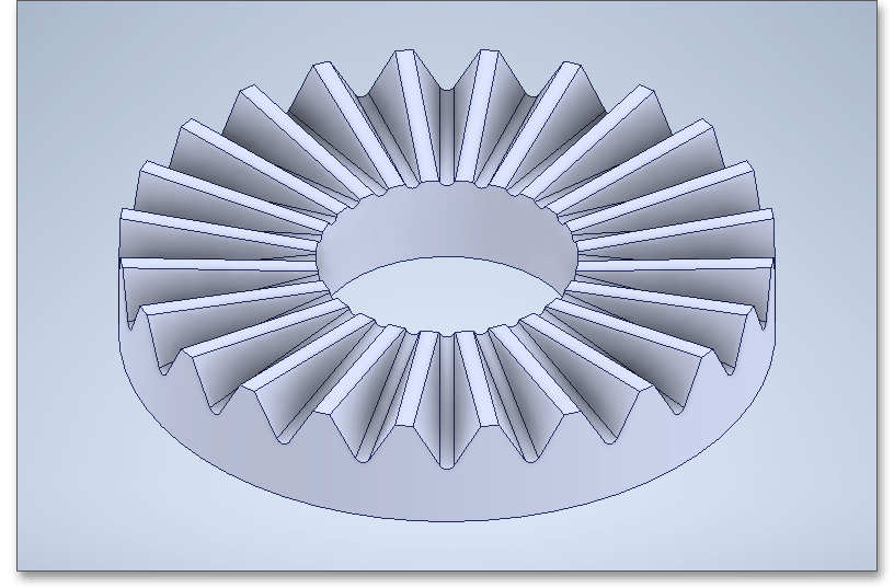
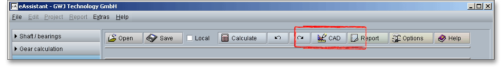
The top menu bar of the eAssistant software provides the button ‘CAD’.
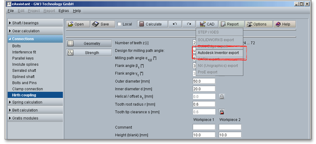
The eAssistant plugin for various CAD systems (e.g., SOLIDWORKS, Solid Edge, Autodesk Inventor) enables
you to combine calculation and design very easily. On the basis of the eAssistant calculation, you can create
the hirth coupling as a 3D part within seconds.
Based on your eAssistant calculation, you can generate the Hirth coupling as a 3D part within seconds. Click the button ‘CAD’ and select the appropriate CAD system from the list.
Open your CAD system. The top menu bar of the CAD system shows a button called ‘eAssistant’. Please click
this button to start the generation of the 3D model.
Please note: Before you can start using the eAssistant CAD plugin, you need to download and install the CAD
plugin from our web site www.eAssistant.eu.
With just one click, the design table with all manufacturing details can be placed on the drawing.
Please note: In case you need further information about the eAssistant eAssistant CAD plugin, please feel free
to contact us. The web site www.eAssistant.eu also contains detailed information. There you can also find the
eAssistant CAD plugin manuals for the various CAD systems.
For further information, please visit our web site www.eAssistant.eu or read the eAssistant CAD plugin
manual.
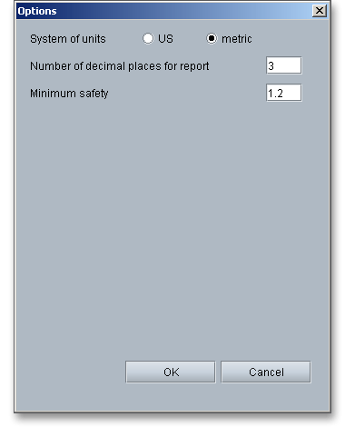
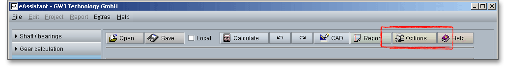
Click on the button ‘Options’ in the top menu bar to change some general settings.
Modify the minimum safety as well as the unit system. The number of decimal places for the output of the numerical values in the report can also be changed.