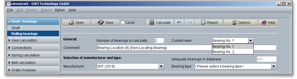
Please login with your username and your password. To start the calculation module for rolling bearings, please click the menu item ‘Shaft/Bearings’ on the left side and then select ‘Rolling bearings calculation’.
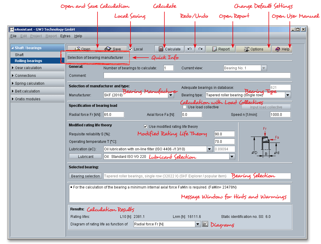
Please Note: All results will be calculated during every input and will be displayed in the result panel. A recalculation occurs after every data input. Any changes that are made to the user interface take effect immediately. Press the Enter key or move to the next input field to complete the input. Alternatively, use the Tab key to jump from field to field or click the ‘Calculate’ button after every input.
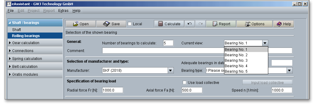
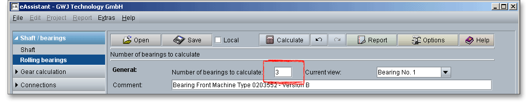
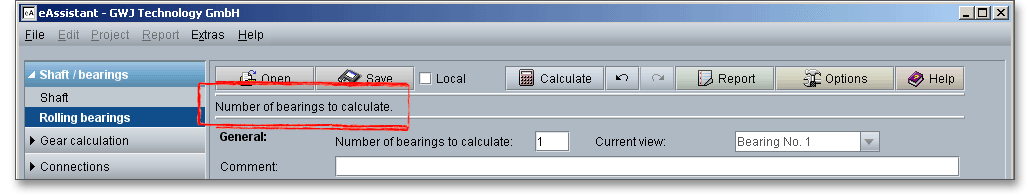
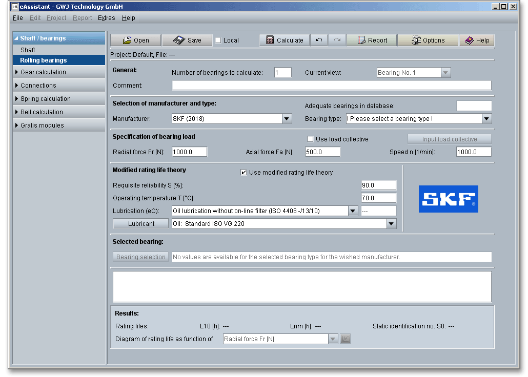
The calculation module allows to define any number of bearings.
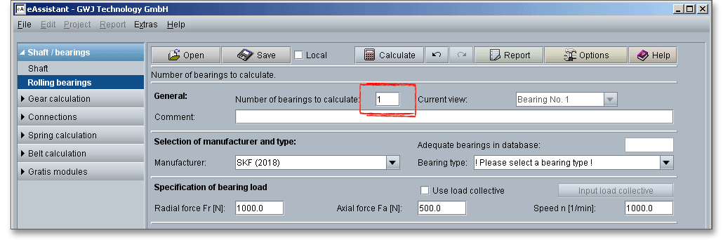
The following listbox ‘Current view’ allows you to select between the several bearings.
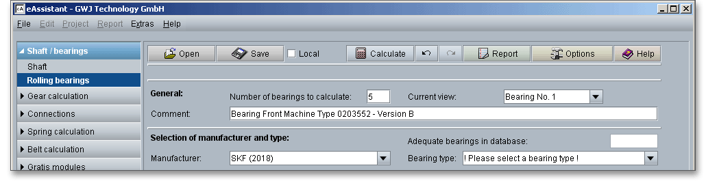
You can add a description or a short comment to the bearing.
If you want to delete a bearing, please enter the new number of bearings and confirm the input with the Enter key.
Now select the bearing you want to delete and click the button ‘Delete the selected bearings!’.
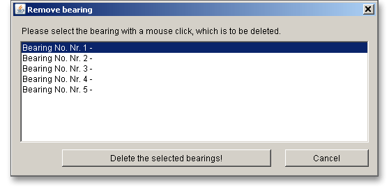
Please note: If you want to delete multiple bearings at once, select the bearings you want to delete. Click the
button ‘Delete the selected bearings!’.
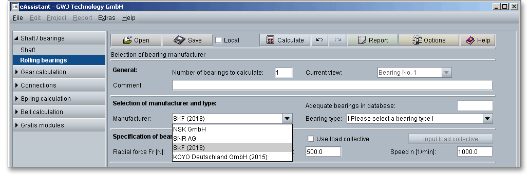
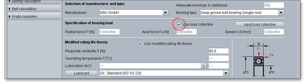
The extensive bearing database provides over 20,000 bearings from different manufacturers. Select the bearing manufacturer (NSK, SNR, SKF, KOYO) from the listbox.
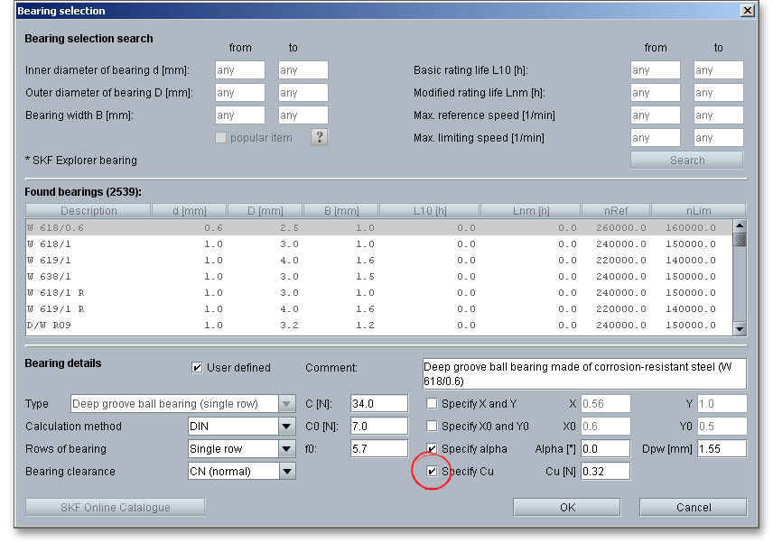
The stress of the raceway fatigue depends primarily on the internal load distribution in the bearing. In order to simplify the calculation, the fatigue limit load \(C_{u}\) was introduced. Usually, the bearing manufacturer specifies the values for \(C_{u}\). In case these values are missing, the equations defined in DIN ISO 281 will be used. These equations apply for bearings \(D_{pw} <\) 150 mm.
Roller bearings:
\[C_{ur} \approx \frac {1}{8.2} \times C_{0r} \quad \mbox {and}\quad C_{ua} \approx \frac {1}{8.2} \times C_{0a}\]
Ball bearings:
\[C_{ur} \approx \frac {1}{27} \times C_{0r} \quad \mbox {and}\quad C_{ua} \approx \frac {1}{27} \times C_{0a}\]
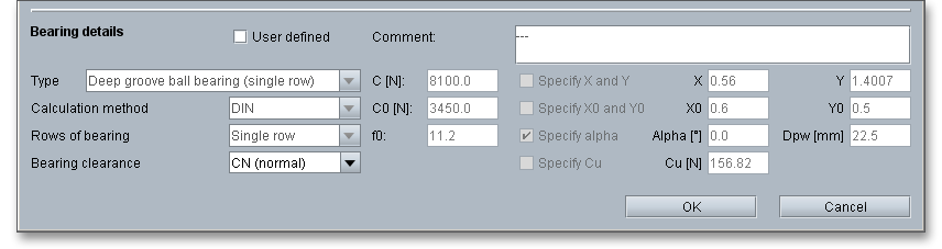
The bearing selection allows to define your own fatigue limit load. Open the bearing selection and activate ‘User defined’, select the option ‘Specify \(C_{u}\)’. Enter the value for the fatigue limit load. If you do not specify the fatigue limit load or if the bearing selection does not include the fatigue limit load, then fatigue limit load is calculated in accordance with DIN ISO 281.
Rolling bearings are ready-to-fit machine elements. Rolling bearings are an assembly of several parts - rings
with raceway, rolling elements (a set of balls or rollers) and a cage which separates the rolling elements and
holds them in place. The rings of radial rolling bearings are called inner and outer rings. Generally, the outer ring
fits on the housing, the inner ring on the shaft. For axial bearings, the inner ring is called shaft
washer and the outer ring is called housing washer. Because of the very small contact surface,
balls cause high Hertzian stresses. Rollers have lower Hertzian stresses and are suitable for high
loads.
Rolling bearings can be also classified according to the direction in which the load is applied. Radial bearings carry radial loads and axial bearings carry axial loads. Rolling bearings divide into two main classifications: ball bearings and roller bearings. A further feature is how the bearings guide a shaft. There are bearings that allow axial displacements and bearings that guide a shaft in one or both axial directions. Types of rolling bearings are given in the following figure below.
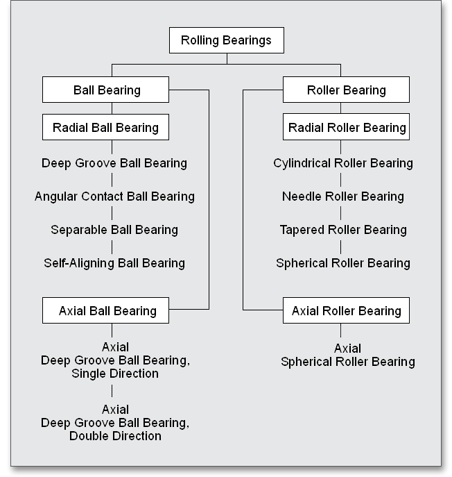
The following bearing types can be selected from the listbox:
Please Note: There is a graphical representation for every bearing type.
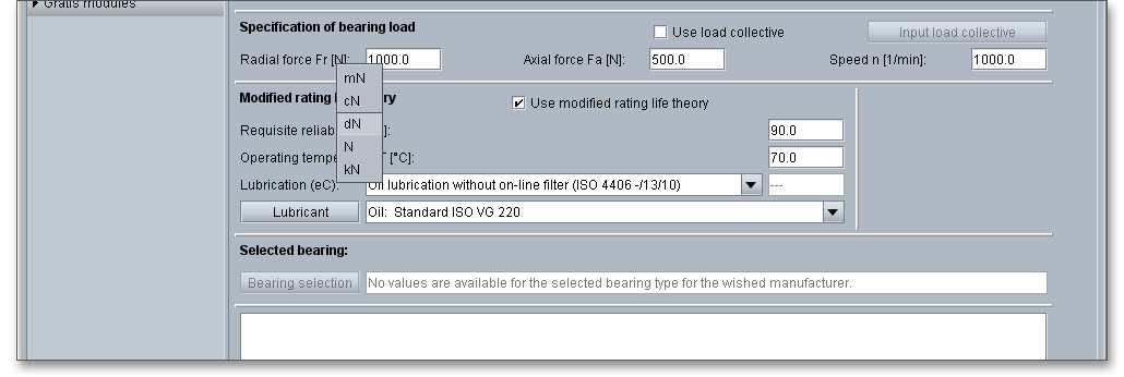
Here you can define the radial force, the axial force and speed.

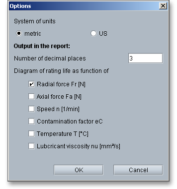
eAssistant provides two unit systems: the metric system and the U.S. customary unit system. You can quickly switch between the units. To select the unit system, click the button ‘Options’ and decide for a unit.
It is also possible to change the unit by clicking the label field. When you click the label field, a context menu will open providing all available units within the unit system. The change should take effect immediately. All settings will be saved to the calculation file. As soon as you select a unit, the current field value will be converted automatically into the chosen unit.
If you activate the option ‘Use load collective’, you can consider load collectives for your calculation.
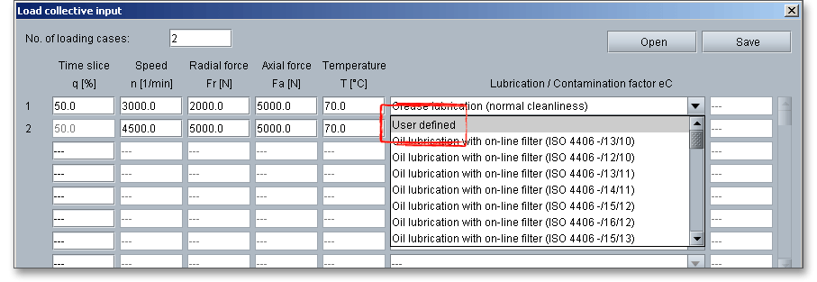
You can define any number of load cases. For every loading case a specification for time slice, speed, radial force, axial force, temperature and cleanness is possible. A listbox shows you the degree of impurities.
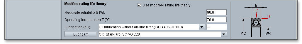
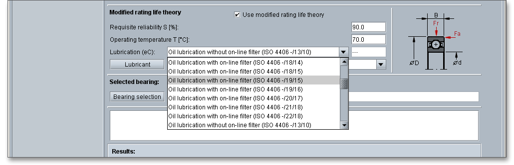
The respective lubrication method or the contamination coefficient is available by using the listbox. If you select ‘User defined’ from the listbox, you can enter your own contamination factor \(e_{c}\).
The load collectives can be opened and saved independently from the underlying bearing calculation. For that purpose use the button ‘Open’ and ‘Save’.
Please note: With the definition of the load cases, the entries for the modified rating life will be
set.
According to DIN ISO 281, contaminations in the lubricant cause dents in the raceways and can damage the smooth surfaces of the bearing components. Rough surfaces tent to cause stress concentrations resulting in shorter bearing life. The lubricant contamination factor \(e_{c}\) considers the influence of the contaminants on the rating life.
| Lubricant Contamination Factor \(e_{c}\) According to DIN ISO 2811
| ||
| Grade of Contaminations | Lubricant Contamination Factor \(e_{c}\)
| |
|
| \(D_{pw} < 100\ mm\) | \(D_{pw} \geq 100\ mm\) |
| Extreme Cleanliness: | 1 | 1 |
| Particle size within the height of the lubricant film under laboratory conditions | ||
| High Cleanliness: | 0.8 to 0.6 | 0.9 to 0.8 |
| Oil is filtered by extremely fine filters, sealed, greased bearings | ||
| Standard Cleanliness: | 0.6 to 0.5 | 0.8 to 0.6 |
| Oil is filtered by fine filters, greased bearings with shields | ||
| Slight Contaminations: | 0.5 to 0.3 | 0.6 to 0.4 |
| Slight contamination of oil | ||
| Typical Contaminations: | 0.3 to 0.1 | 0.4 to 0.2 |
| Bearing contaminated with abraded material from other machine elements | ||
| Strong Contaminations: | 0.1 to 0 | 0.1 to 0 |
| Bearing environment is strongly contaminated, inadequate sealing of bearing arrangement | ||
| Very strong contaminations | 0 | 0 |
| 1 from: DIN ISO 281 Rolling Bearings - Dynamic Load Ratings and Rating Life (ISO 281: 2007),
2010, p. 33, table 13
| ||
The values given in the table above apply for solid particles. Other contaminations such as water or liquids are
not taken into account.
The following factors have a significant influence on the rating life of bearings:
The calculation method for the nominal rating life \(L_{10}\) is defined in DIN ISO 281. The rating life \(L_{10}\) of a large group of identical ball bearings is the life in millions of revolutions that 90 percent of the group will complete or exceed before material fatigue occurs.
| Reference Values for Required Rating Life2
| |
| Vehicles (full load) | |
| Passenger cars | 900 to 1,600 hours |
| Trucks and busses | 1,700 to 9,000 hours |
| Railway vehicles | |
| Axle bearing mine cars | 10,000 to 34,000 hours |
| Streetcars | 30,000 to 50,000 hours |
| Passenger carriages | 20,000 to 34,000 hours |
| Locomotives | 30,000 to 100,000 hours |
| Gears for railway vehicles | 15,000 to 70,000 hours |
| Agricultural machinery | 2,000 to 5,000 hours |
| Construction machinery | 1,000 to 5,000 hours |
| Electric motors for household appliances | 1,500 to 4,000 hours |
| Series engines | 20,000 to 40,000 hours |
| Large engines | 50,000 to 100,000 hours |
| Machine tools | 15,000 to 80,000 hours |
| Gears for general mechanical engineering | 4,000 to 20,000 hours |
| Large gearboxes | 20,000 to 80,000 hours |
| Ventilators, fans | 12,000 to 80,000 hours |
| Gear pumps | 500 to 8,000 hours |
| Crushers, mills, sieves | 12,000 to 50,000 hours |
| Paper and printing machines | 50,000 to 200,000 hours |
| Textile machinery | 10,000 to 50,000 hours |
| 2 from: Taschenbuch fuer den Maschinenbau/Dubbel, 1997, p. G173, appx. G4 table 2
| |
In some cases it can be sufficient to determine the nominal rating life. The nominal rating life is associated with
90 percent reliability. But for some applications it can be very insightful to determine the rating life for a higher
reliability and to consider the influence of the bearing quality and operating conditions. By using the modified
rating life, these criteria can be further investigated.
The modified rating life theory is activated by default. If the load collectives are not activated, then enter you individual specifications for the requisite reliability, operating temperature or cleanness. You can enter your own cleanness factor for the grade of contaminations. Select ‘User-defined’ from the listbox.
The purpose of lubricating the bearing is to cover the rolling and sliding contact surfaces with a
thin oil film to avoid direct metal to metal contact. The most important function of a lubricant is to
protect the sliding and rolling surfaces from wear and friction. The extensive lubricant database
provides different kind of oils and greases for the calculation of the modified rating life. In case you are
missing the right lubricant for your calculation, please define your own lubricant. The lubrication has a
considerable influence on the operating life of the bearing. Oil and greases are the most common
lubricants for rolling bearings. In special cases, rolling bearings are lubricated with solid or dry
lubricants. The choice of lubrication and lubricant depends on speed and operating temperature of the
bearing. The selection of the lubrication method depends on operating conditions and environmental
influences.
Most rolling bearings are lubricated using grease. Grease lubrication consists of a base oil and a thickener.
There are two main types of base oil: mineral and synthetic oil. The thickener and the additives in the grease
enhance the lubricating effect so that no life reduction has to be expected. Calcium, aluminum, sodium and
lithium soap greases can be used for heavy-loaded rolling bearings. Most of greases contain additives in order
to improve the properties of the grease. It is necessary to renew the lubricating grease at regular
intervals. The lubrication interval depends on many factors, such as the grease type, bearing and
working conditions. Grease lubrication is easy to handle and provides excellent protection against
contamination.
Grease lubrication is widely used. Approximately 90 percent of all bearings are lubricated with grease. The main advantages of grease lubrication are (according to Braendlein ‘Die Waelzlagerpraxis’):
Oil lubrication is generally used for rolling bearings when adjacent system components are lubricated
with oil or when cooling is required. Oil lubrication is also used when very high speeds or very
high loads preclude the use of grease as a lubricant. The selection of the oil type depends on the
requirements of the components. For the lubrication of rolling bearings, mineral oils and synthetic oils
are suitable. Oils with a mineral oil base are most common. The better the contact surfaces are
separated by the lubricating film, the better the bearing life and safety against wear. The lubricating
film thickness increases with the oil viscosity, so an oil with a high operating viscosity should be
selected.
The viscosity, as well the dependence of the density and viscosity on the pressure and the temperature play an
important role for the technical application of lubricants. Viscosity is one very important property of a lubricant
and determines the oils lubricating efficiency. Thin oils have low viscosities while thicker oils have high
viscosities. In addition to the base oil viscosity, thickener and additives have a decisive influence on greases.
The density of lubricating oils is between 0.86 and 0.93 \(kg/dm^{3}\). The viscosity of the oil decreases with increasing
temperature. As the temperature falls, the viscosity of the oil increases. It is therefore necessary to indicate the
temperature dependence of an oil’s kinematic viscosity. The viscosity at \(40^\circ \)C and at \(100^\circ \)C (for thicker oils) are typical
values.
About 150 products of the following manufacturer are available:
Select a lubricant from the listbox.
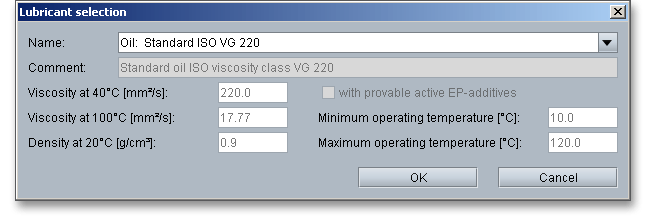
Select the lubricant directly from the listbox or click the button ‘Lubricant’.
The lubricant selection is opened. Here you get all information to the selected lubricant.
The two cursor keys ‘Up’ and ‘Down’ of your keyboard allows you to navigate through the lubricant database, so
you can compare the different lubricant values with each other.
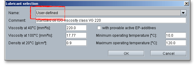
In case you cannot find the lubricant you are looking for in our extensive database, simply define your individual lubricant. You will find the entry ‘User-defined’ in the listbox. If you select this option, the according input fields will be enabled, so that you can specify your own input values or add a comment. In order to confirm your inputs, click the button ‘OK’. Please be advised that changing the lubricant will delete your defined inputs and you have to enter the inputs again.
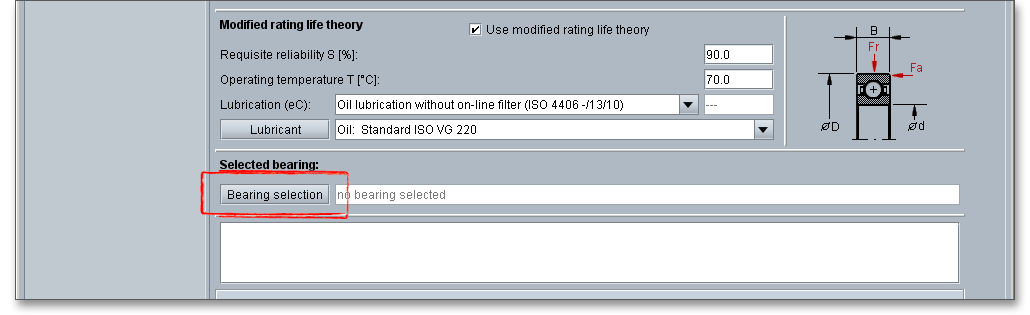
After you choose the manufacturer and the bearing type, please select the bearing from the list or use bearing selection search to find the right bearing. Click the button ‘Bearing selection’.
Click the button ‘Bearing selection’ to open the bearing database.
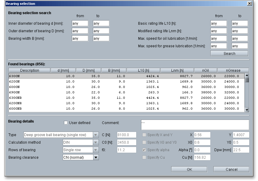
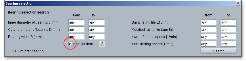
We have an extensive range of bearings but search filters have been developed to assist in searching the extensive amount of bearings and to quickly find the bearing you are looking for. You might filter bearing types by diameter or rating life so that you can only see bearing types with this particular diameter or rating life. The following parameters can be provided to further refine the search:
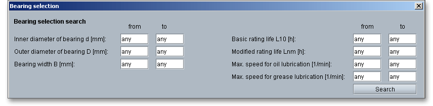
Use the Tab key to move from input field to input field. The more values you enter into the input fields the more you will narrow your search. If you have already entered values into the input fields and you now wish to add again an arbitrary inner or outer diameter, then delete your own value and click on any input field. You can also press the Tab key. The option ‘Any’ will then be used again and the number of bearings also increases again. After entering all reqired data, click the ‘Search’ button.
With the display of the found bearings you can re-sort the list by clicking on the column headers. If the bearings are to be sorted in reverse order, then click on the column headers again.
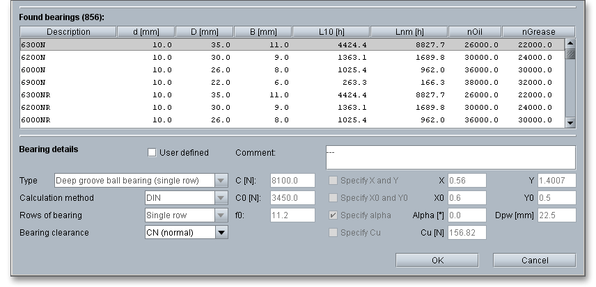
Here you can get additional information on the selected bearing.
Please note: For radial deep groove ball bearings the selection for increased bearing clearance C3 or C4 is
additionally integrated in the bearing selection search, which is taken into account in the rating life calculation.
When using this option, it should be noted that the bearing clearance should be selected which is present in
operation after the bearing has been fitted.
For SKF bearing data, there is a filter function that simplifies finding common bearings (button ‘popular item’) in the bearing selection search. In addition, SKF Explorer bearings are marked accordingly and the corresponding page of the SKF online catalog can be opened for the selected bearing. The appropriate button is located in the bearing database in the lower left corner. After determining the desired bearing type, it may be helpful to select a suitable bearing from the manufacturer’s range of common bearings. Popular items have a high level of availability and generally provide a cost-effective solution. SKF Explorer bearings are designed for heavy-duty applications. They run with less friction and have longer rating lifes than standard rolling bearings.
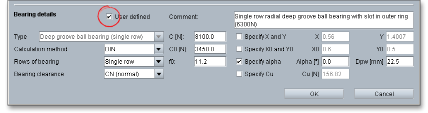
You can select a bearing from the bearing database or you can define your individual bearing. Activate the option ‘User defined’, the input fields will be enabled and you can enter your own input values. Please confirm your inputs with the ‘OK’ button.
The calculation module provides a message window. This message window displays detailed information, helpful hints or warnings about problems. One of the main benefits of the program is that the software provides suggestions for correcting errors during the data input. If you check the message window carefully for any errors or warnings and follow the hints, you are able to find a solution to quickly resolve calculation problems.
The quick info feature gives you additional information about all input fields and buttons. Move the mouse pointer to an input field or a button, then you will get some additional information. This information will be displayed in the quick info line.
All results will be calculated during every input and will be displayed in the result panel. A recalculation occurs after every data input. Any changes that are made to the user interface take effect immediately. Press the ‘Enter’ key or move to the next input field to complete the input. Alternatively, use the Tab key to jump from field to field or click the ‘Calculate’ button after every input. Your entries will be also confirmed and the calculation results will displayed automatically.
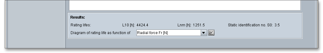
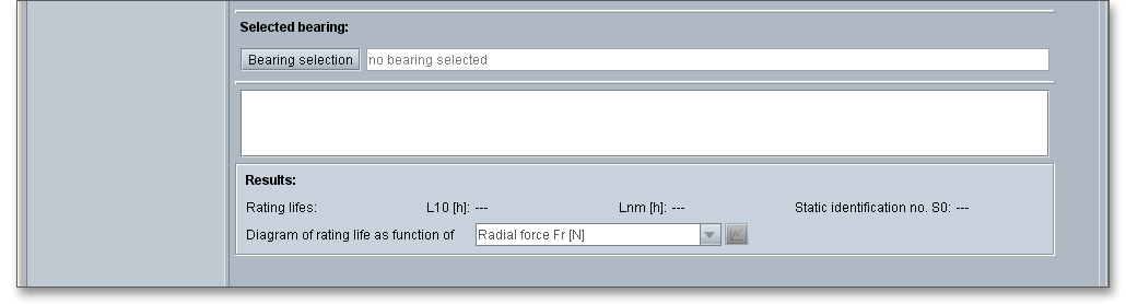
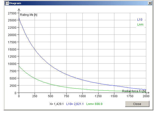
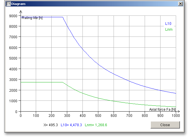
For a further illustration the following diagrams are available:
The listbox contains the different diagrams and you can decide which diagram should be displayed.
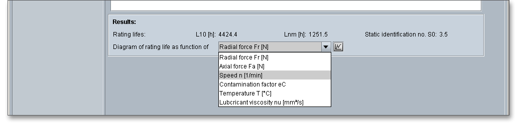
Choose the diagram and click on the button ‘Diagram’ next to the listbox.
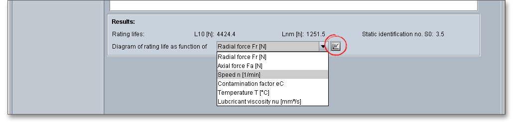
The diagram with the values for the rating life and for the modified rating life will be displayed immediately.
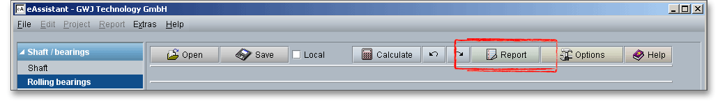
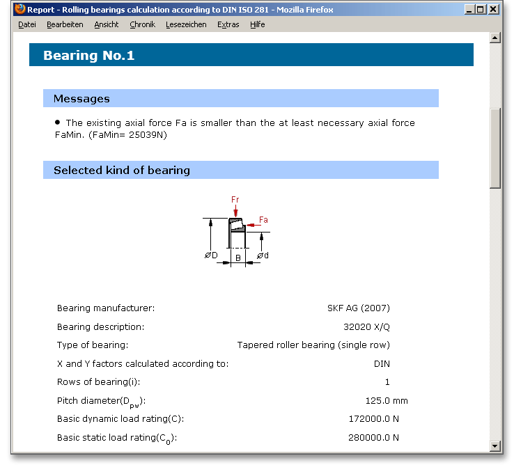
After the completion of your calculation, you can create a calculation report. Click on the ‘Report’ button.
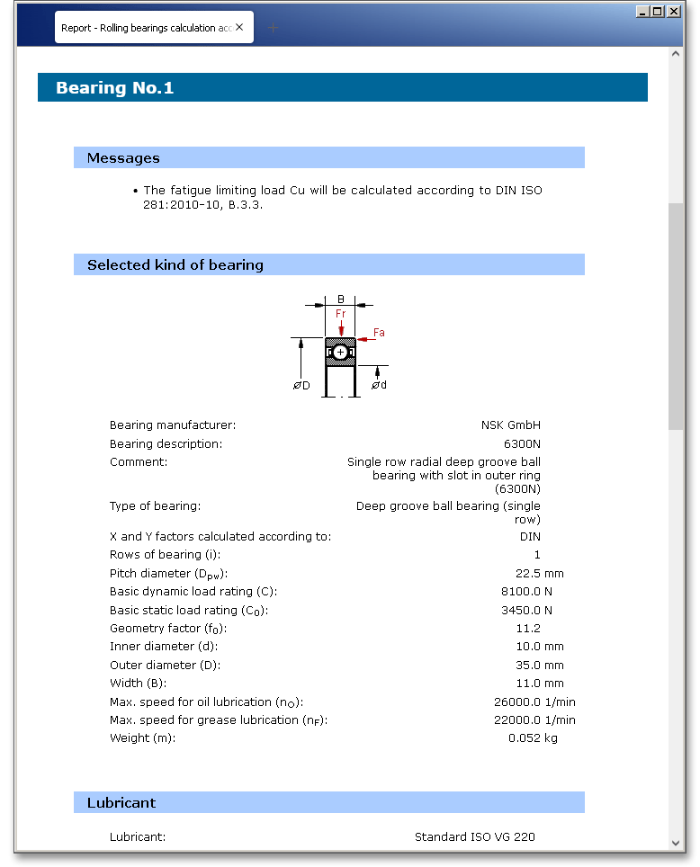
You can navigate through the report via the table of contents that provides links to the input values, results and figures. This calculation report contains all input data, the calculation method as well as all detailed results. The report is available in HTML and PDF format. The calculation report saved in HTML format, can be opened in a web browser or in Word for Windows.
You may also print or save the calculation report:
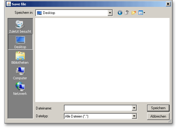
When the calculation is finished, it is easy to save the calculation. You can save your calculation either to the eAssistant server or to your computer. Click on the button ‘Save’.

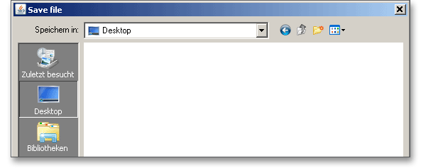
Before you can save the calculation to your computer, you need to activate the checkbox ‘Local’ in the calculation module. A standard Windows dialog for saving files will appear. Now you will be able to save the calculation to your computer.

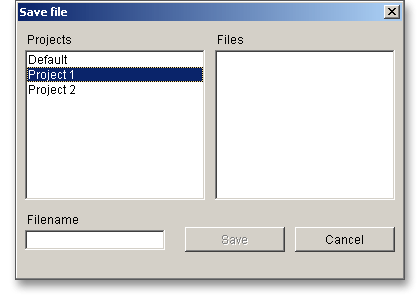
In case you do not activate the option in order to save your files locally, then a new window is opened and you can save the calculation to the eAssistant server. Please enter a name into the input field ‘Filename’ and click on the button ‘Save’.

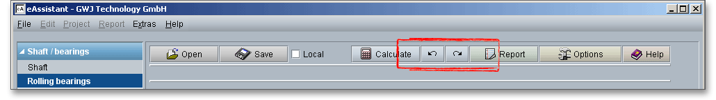
The button ‘Undo’ allows you to reset your input to an older state. The button ‘Redo’ reverses the undo.
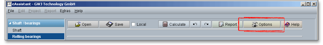
Click the button ‘Options’ to change the default settings, for example the unit system or the number of decimal places for the calculation report. The unit can also be changed directly for each individual input value. Simply click on the label of the corresponding input field and select the unit from the context menu. You will see the change of the unit of measurement immediately in the label of the input field. The current field value will be converted to the corresponding unit.
A new window opens up that provides a possibility to choose the diagrams that shall be added to the calculation report.
Please login with your username and your password. To start the calculation module for rolling bearings, please click the menu item ‘Shaft/Bearings’ on the left side and then select ‘Rolling bearings’.
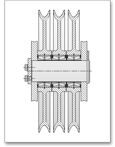
The wrap angle for rope sheaves of pulley blocks is \(180^{\circ }\). Therefore, the load on the bearing is twice the rope pull.
The axial forces and the resulting moments are low. When the diagonal pull is \(5^{\circ }\), then the axial forces have to be
considered for the calculation of the rating life. Adequate bearing spread for load accommodation is
achieved by mounting either two bearings or one double-row bearing. In the following example
the rating life and modified rating life are to be calculated. We have taken this example from: J.
Braendlein: Die Waelzlagerpraxis: Handbuch zur Berechnung und Gestaltung von Waelzlagern (1995, p.
466-470).
Please enter the following input values:
| Bearing load | 65 kN |
| Type of bearing | Tapered roller bearing (single row) |
| Speed n | 30 min\(^{-1}\) |
| Built-in bearing | Tapered roller bearing (100 x 150 x 67) |
| For-life lubrication | Grease with EP-additive |
Illustration of a rope sheave of a pulley block including the tapered roller bearing. (The following figure: J. Braendlein: Die Waelzlagerpraxis, p. 467).
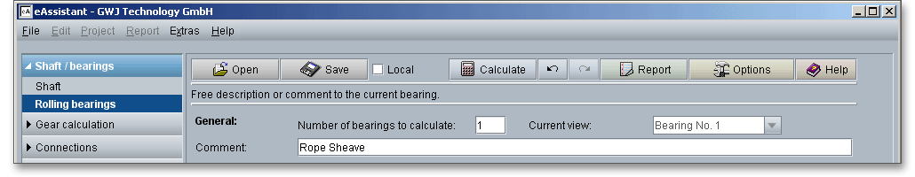
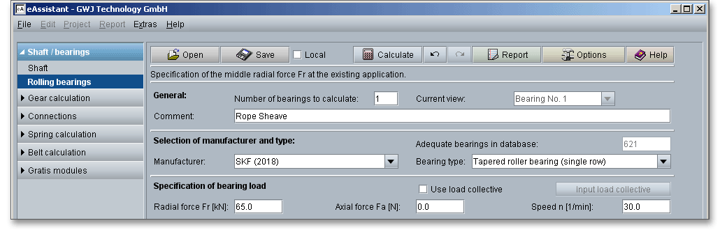
In this example we would like to calculate one bearing of a tapered roller bearing pair. When you open the calculation module, usually one bearing is shown. So it is not necessary to change the number of the bearings. You can enter a description into the comment field, for example ‘Bearing of the rope sheave’.
The extensive bearing database provides over 20,000 bearings from different manufacturers. Select the bearing manufacturer ‘SKF 2007’ from the listbox. Next, choose the bearing type ‘Tapered roller bearing (single row)’.
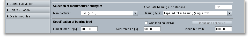
Enter the values for the bearing load now. Please keep in mind that the values will be entered in ‘kN’. Right-clicking allows you to change the unit.
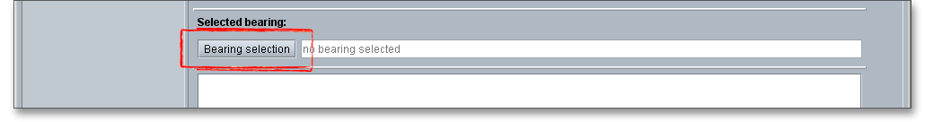
Click on the button ‘Bearing selection’ to open the bearing database.
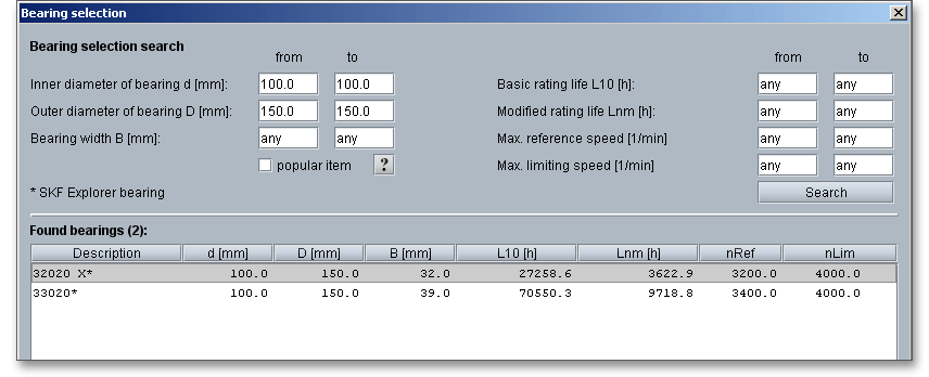
There are ‘578’ bearings in the database right now. Search filters have been developed to assist in searching this extensive amount of bearings and to quickly find the bearing you are looking for. You can filter the bearing types by the inner and outer diameter so that you can only see bearing types with this particular diameter. Enter the inner and outer diameter and click the button ‘Search’.
| Inner diameter of bearing | = 100 mm |
| Outer diameter of bearing | = 150 mm |
Select the bearing ‘32020 X*’ and confirm with the button ‘OK’.
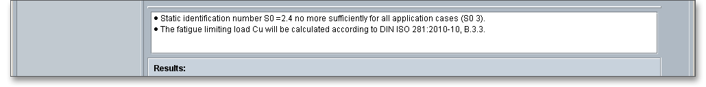
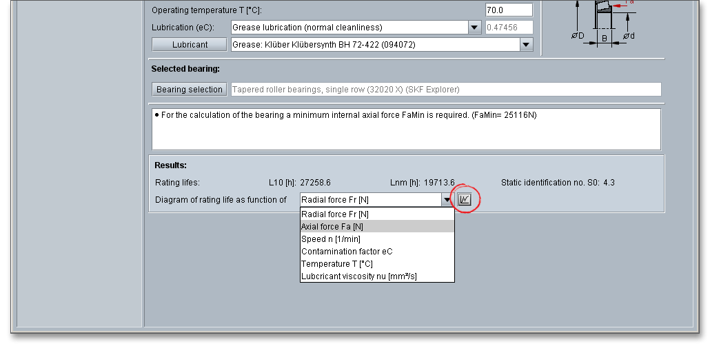
All results will be calculated during every input and will be displayed in the result panel. A recalculation occurs after every data input. Any changes that are made to the user interface take effect immediately. First, you get the result for the rating life as well as the static identification number.
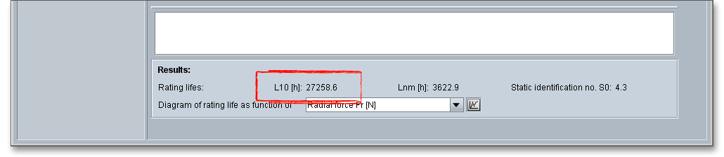
The result of the rating life is \(L_{10}\) = 27.258,6 h
For rope sheaves, a rating life from 5,000 to 20,000 hours is required. The bearing is sufficiently dimensioned. You will find a note in the message window but you can ignore this message. When the pair is fitted together, then the correct axial clearance and the necessary axial force for the tapered roller bearing occur.
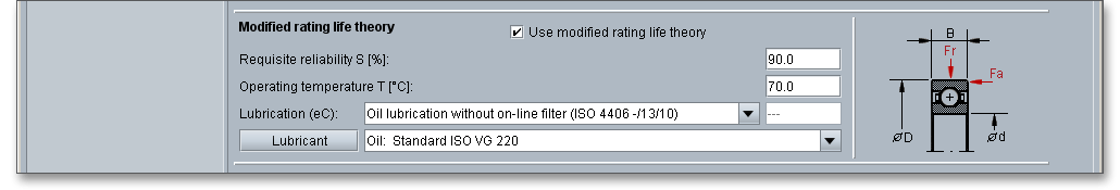
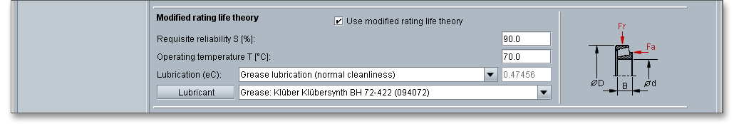
After you get the result for the rating life, please have a look at the modified rating life theory \(L_{nm}\) regarding the
operating conditions (lubrication, clearance). The option ‘Use modified rating life theory’ is activated by
default.
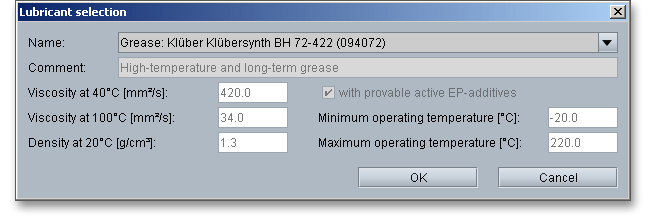
Now you an define the requisite reliability and the cleanness as well as a lubricant. Please select the grease ‘Klueber Kluebersynth BMQ 72-162 (094073)’. Select this lubricant directly from the listbox. If you need detailed information, please click on the button ‘Lubricant’.
Clicking the button ‘Lubricant’ opens the lubricant database. Here you can see that the grease contains active EP additive.
Next, you have to estimate the influence of possible impurities by using the cleanness factor. Actually, it is assumed that the ‘highest cleanness’ is used for sealed and greased bearings (for-life-lubrication). But during the entire operating time, a certain wear of the seals could occur which can let light impurities into the bearing. In this case you can assume light impurities. Therefore, choose ‘Light impurities’ from the listbox.
Now you get immediately the result for the modified rating life.
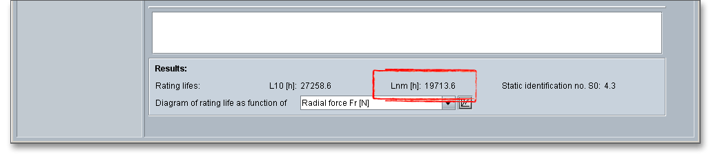
The result of the modified rating life is \(L_{nm}\) = 19.713,6 h. Finally, the modified rating life \(L_{nm}\) is in the range of the rating
life \(L_{10}\).
Please note: Press the ‘Up’ and ‘Down’ arrow to move through the listbox of cleanness parameters. Moving
through the listbox changes the modified rating life and the results will be displayed immediately in the result
panel, making it very easy to compare the modified rating life with different levels of cleanness. You can also
navigate through the lubricant listbox.
Click on the button ‘Diagram’ next to the listbox. The diagram includes the values for the rating life and for the modified rating life. The exact values can be selected directly from the graphical representation. Clicking the ‘Close’ button leads you back to the main mask and you can open another diagram. Use the ‘Options’ button to specify which diagrams should be displayed in your calculation report.
After the completion of your calculation, you can create a calculation report. Click on the ‘Report’ button.

You can navigate through the report via the table of contents that provides links to the input values, results and figures. This calculation report contains all input data, the calculation method as well as all detailed results. The report is available in HTML and PDF format. The calculation report saved in HTML format, can be opened in a web browser or in Word for Windows.
You may also print or save the calculation report:
When the calculation is finished, it is easy to save the calculation. You can save your calculation either to the eAssistant server or to your computer. Click on the button ‘Save’.

Before you can save the calculation to your computer, you need to activate the checkbox ‘Local’ in the calculation module. A standard Windows dialog for saving files will appear. Now you will be able to save the calculation to your computer.
In case you do not activate the option in order to save your files locally, then a new window is opened and you can save the calculation to the eAssistant server. Please enter a name into the input field ‘Filename’ and click on the button ‘Save’.

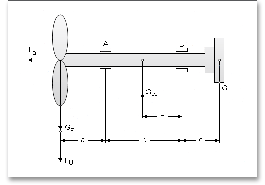
The impeller of fans can be arranged either between two bearings or in an overhung position. The impeller of
small and medium-sized fans is generally overhung. Two separated plummer block housings are suitable for
supporting the fan drive shaft.
This calculation example we have taken from: J. Braendlein: Die Waelzlagerpraxis: Handbuch zur Berechnung und Gestaltung von Waelzlagern (1995, p. 516-520, figures: p. 517).
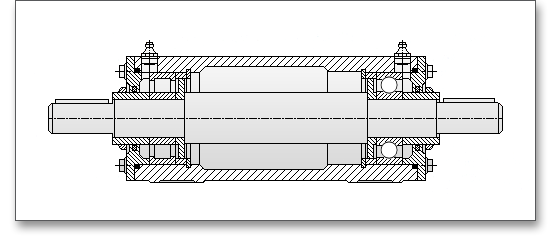
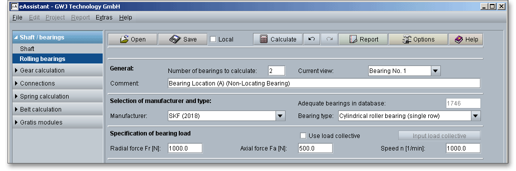
The unit (figure 5.61) contains a cylindrical roller bearing A and a deep groove ball bearing B in one housing (figure 5.62). The bearing diameter is 70 mm.
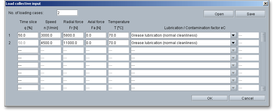
The input values for bearing A (Cylindrical roller bearing NU 314 ECP)
| Load Case No. 1 | Load Case No. 2 |
| Time slice \(q_{1}\) | = 50% | Time slice \(q_{2}\) | = 50% |
| Speed \(n_{1}\) | = 3,000 min-1 | Speed \(n_{2}\) | = 4,500 min-1 |
| Radial force \(F_{r1}\) | = 8,500 N | Radial force \(F_{r2}\) | = 11,000 N |
| Axial force \(F_{a1}\) | = 0 N | Axial force \(F_{a2}\) | = 0 N |
| Temperature \(T_{1}\) | = \(70^{\circ }\)C | Temperature \(T_{2}\) | = \(70^{\circ }\)C |
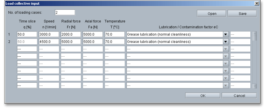
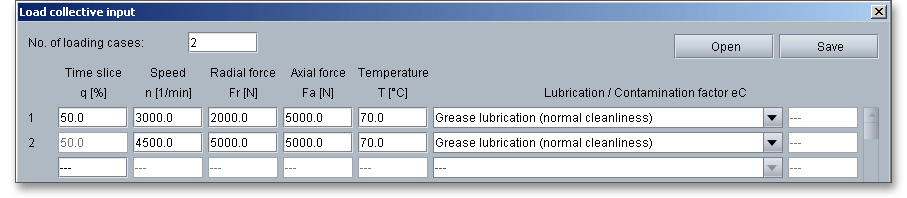
All input values for bearing B (deep groove ball bearing 6314)
| Load Case No. 1 | Load Case No. 2 |
| Time slice \(q_{1}\) | = 50% | Time slice \(q_{2}\) | = 50% |
| Speed \(n_{1}\) | = 3,000 min-1 | Speed \(n_{2}\) | = 4,500 min-1 |
| Radial force \(F_{r1}\) | = 2,000 N | Radial force \(F_{r2}\) | = 5,000 N |
| Axial force \(F_{a1}\) | = 5,000 N | Axial force \(F_{a2}\) | = 5,000 N |
| Temperature \(T_{1}\) | = \(70^{\circ }\)C | Temperature \(T_{2}\) | = \(70^{\circ }\)C |
In this example we want to calculate the rating life of the cylindrical roller bearing and the deep groove ball bearing. We have to different bearings and we need to change the number of bearings. So enter ‘2’ into the input field ‘Number of bearings to calculate’. Please calculate the bearings one after another separately. The listbox ‘Current view’ allows you to switch between the two bearings.
Add a comment for the first bearing.
Now select the manufacturer ‘SKF’. Choose the cylindrical roller bearing from the listbox.
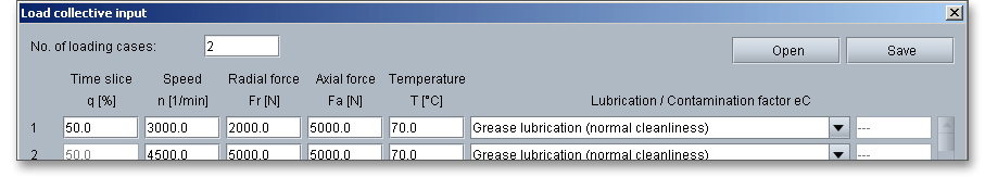
Define the load collective for the first bearing. Activate the option ‘Use load collective’. The input options for the radial and axial force as well as for the speed will be deactivated. Define two load cases for the bearing. Enter the time slice, the radial force, axial force, the temperature and cleanness for each load case. After you made all entries, click the button ‘OK’ to confirm your inputs.
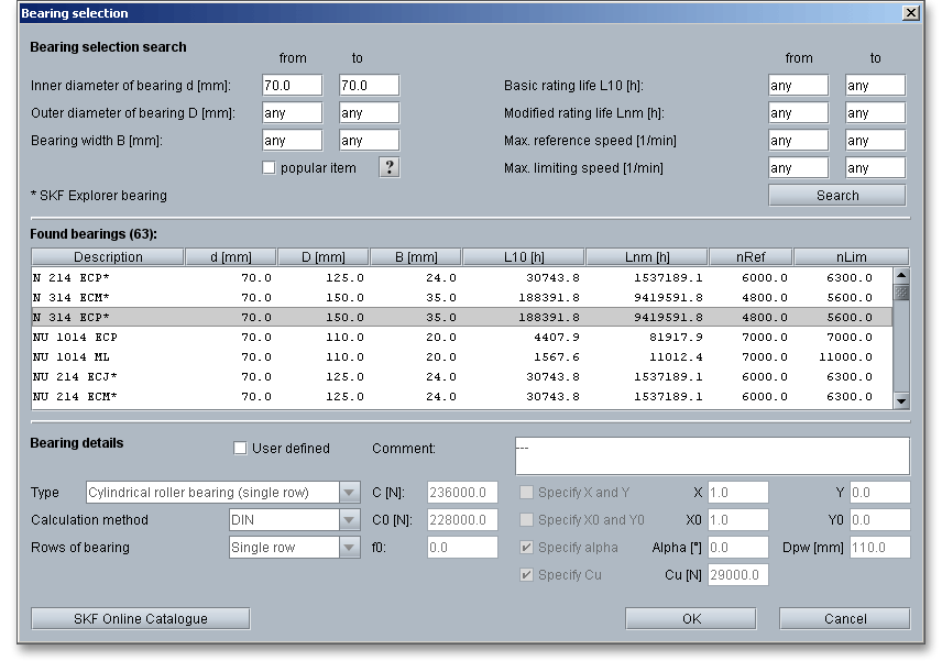
Click on the button ‘Bearing selection’. It is increasingly convenient to use the search filter to quickly find the bearing you are looking for. Enter ‘70 mm’ for the inner diameter and click the button ‘Search’. Now you can choose the cylindrical roller bearing ‘NU 314 ECP’ from the list. Clicking the button ‘OK’ confirms the bearing and leads you back to the main mask.
All results will be calculated during every input and will be displayed in the result panel. A recalculation occurs after every data input. Any changes that are made to the user interface take effect immediately. First, you get the result for the rating life as well as the static identification number.

The result of the rating life is \(L_{10}\) = 188,391.8 h
The cylindrical roller bearing is sufficiently dimensioned.
Calculate now the rating life for the deep groove ball bearing. Please pay attention that you select ‘Bearing No. 2’ from the listbox ‘Current view’. Select the manufacturer ‘SKF’ and the bearing type ‘Deep groove ball bearing (single row)’.
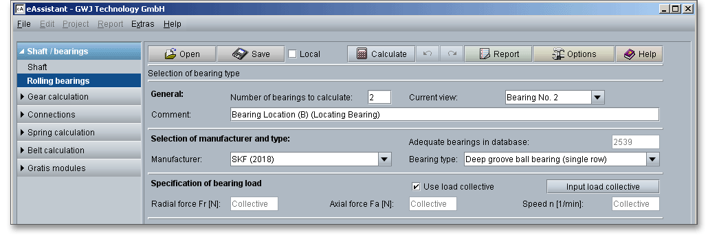
Activate the option ‘Use load collective’ and define the load cases. After you made all entries, click the button ‘OK’ to confirm your inputs.
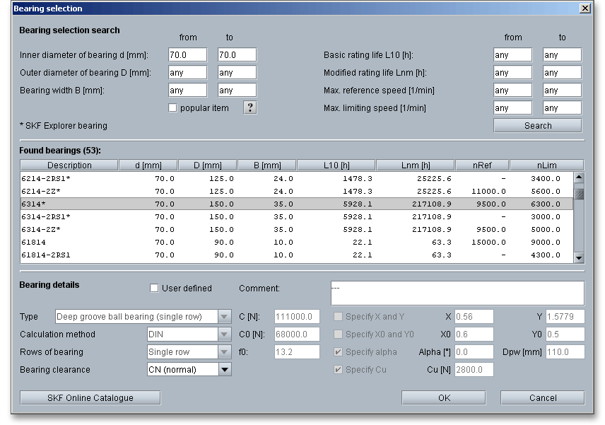
Click on the button ‘Bearing selection’. Choose the bearing ‘6314*’ from the list. It is increasingly convenient to use the search filter to quickly find the bearing you are looking for. Enter ‘70 mm’ for the inner diameter and click the button ‘Search’. Then you can select the bearing ‘6314’ from the list. Clicking the button ‘OK’ confirms the bearing and leads you back to the main mask.
The result for the rating life is \(L_{10}\) = 5.928,1 h
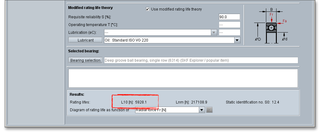
The rating life of the deep groove ball bearing B is lower than the rating life of the cylindrical roller bearing A.
This means that bearing B is subjected to higher stresses than bearing A. At least 220,000 hours are
required for the rating life of deep groove ball bearings. But with this result, the rating life is not
sufficiently dimensioned. It is necessary to take a closer look at the modified rating life \(L_{nm}\) of bearing
B.
The next step is to determine the modified rating life for the deep groove ball bearing. The option ‘Use modified rating theory’ is activated by default. Select the grease ‘Lubcon Turmogrease Highspeed L 252 (K HC P 2/3 K-50)’ from the listbox or click on the button ‘Lubricant’ to open the lubricant selection. Choose the lubricant and confirm with the button ‘OK’.
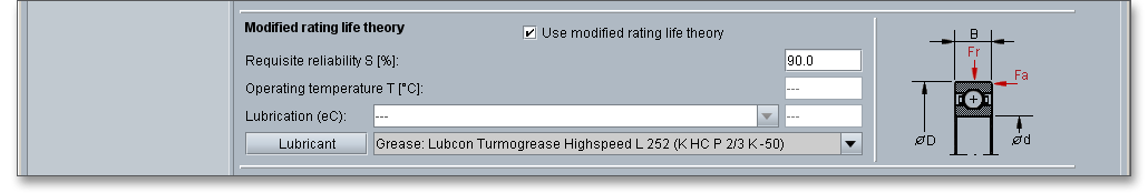
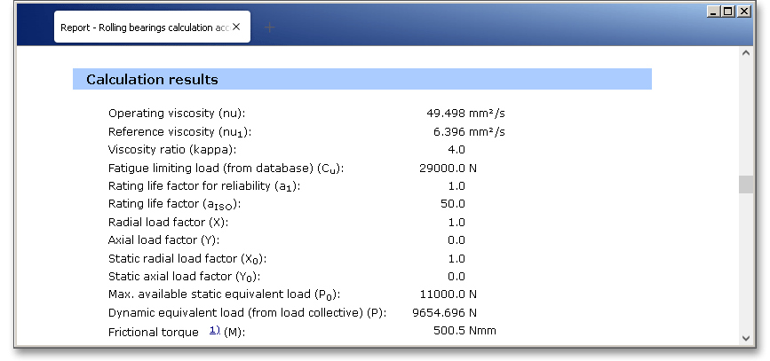
The result of the modified rating life is \(L_{nm}\) = 49.223,4 h.

At least 22,000 hours are required and the bearing is sufficiently dimensioned. For the calculation with
load collectives, you cannot open all diagrams. But you can open the diagram for the lubricant
viscosity.
After the completion of your calculation, you can create a calculation report. Click on the ‘Report’ button. Click the button ‘Options’ and activate the diagram for the ‘Lubricant viscosity’. This diagram will then appear in the calculation report.
You can navigate through the report via the table of contents that provides links to the input values, results and figures. This calculation report contains all input data, the calculation method as well as all detailed results. The report is available in HTML and PDF format. The calculation report saved in HTML format, can be opened in a web browser or in Word for Windows. You may also print or save the calculation report:
When the calculation is finished, it is easy to save the calculation. You can save your calculation either to the eAssistant server or to your computer. Click on the button ‘Save’. Before you can save the calculation to your computer, you need to activate the checkbox ‘Local’ in the calculation module. A standard Windows dialog for saving files will appear. Now you will be able to save the calculation to your computer.
In case you do not activate the option in order to save your files locally, then a new window is opened and you can save the calculation to the eAssistant server. Please enter a name into the input field ‘Filename’ and click on the button ‘Save’.
Our manual is improved continually. Of course we are always interested in your opinion, so we would like to know what you think. We appreciate your feedback and we are looking for ideas, suggestions or criticism. If you have anything to say or if you have any questions, please let us know via telephone +49 (0) 531 129 399-0 or email eAssistant@gwj.de.