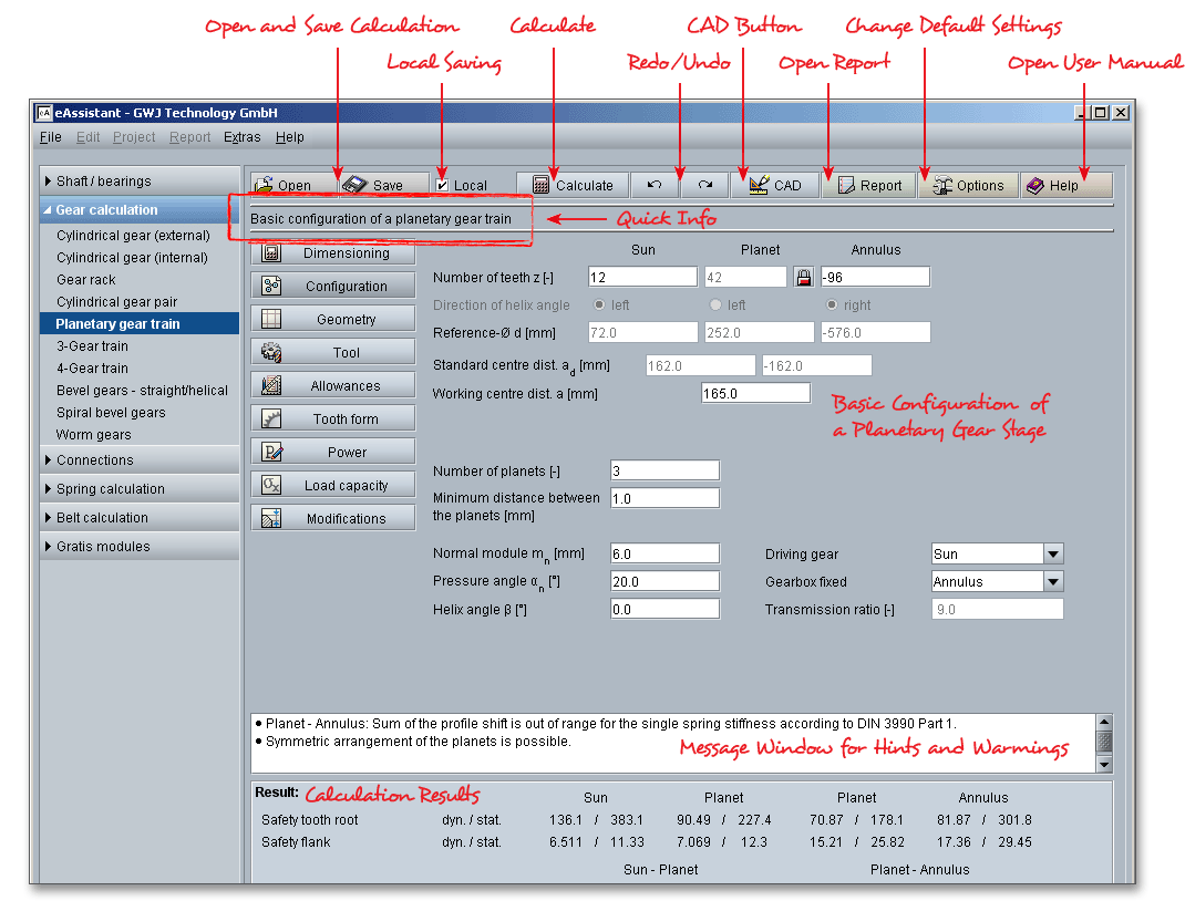
Please login with your username and your password. To start the calculation module for planetary gear trains, please click the menu item ‘Gear calculation’ on the left side and then select ‘Planetary gear train’.

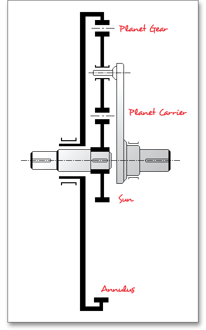
Planetary gear trains are a special type of cylindrical gears. There are different types of planetary gear trains -
simple and compound planetary gear trains. The eAssistant software calculates the simple and typical design of
a planetary gear train. The typical design of planetary gear trains consists of the following elements: external
gear (sun gear), one or more planet gears, an internal gear (annulus gear) and a planetary carrier. The
planetary carrier holds the planet gears. The gear tooth forces are distributed among several planets and are
relatively low. Due to the simple design and good characteristics, planetary gear trains are suitable for many
applications.
Advantages of planetary gear trains:
Disadvantages of planetary gear trains:
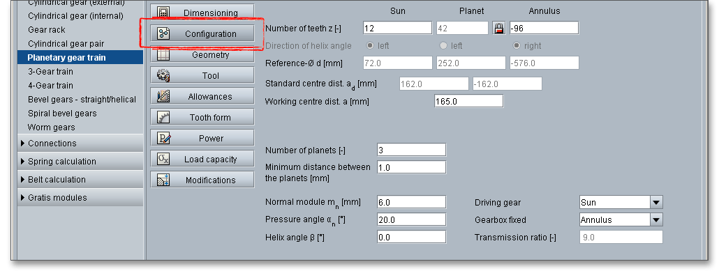
The basic configuration starts with the input of the number of teeth for sun gear, planet gear and annulus gear. The sun gear as well as the planet gears have external teeth and the number of teeth is positive. The number of teeth of the annulus gear is negative. The user manual for cylindrical gears provides some reference values for the selection of the minimum number of teeth and facewidth. The number of teeth of sun gear and annulus gear is usually defined by the transmission ratio and normal module. The number of teeth of the planet gears has no influence on the transmission ratio and the gear characteristics.
Please note: All results will be calculated during every input and will be displayed in the result panel. A
recalculation occurs after every data input. Any changes that are made to the user interface take effect
immediately. In case a minimum safety is not fulfilled, the result will be marked red. Press the Enter key or move
to the next input field to complete the input. Alternatively, use the Tab key to jump from field to field or click the
‘Calculate’ button after every input. Your entries will be also confirmed and the calculation results will displayed
automatically. Click the ‘Tooth form’ button during the configuration of the planetary gear train in order to check
the gear tooth form. Clicking the button ‘Geometry’ and ‘Tooth form’ leads you back to the main
masks.
As soon as you enter a helix angle, you can use the radiobuttons in order to define the direction of the helix angle. For an external gear pair the engaged gearings have different directions, internal gears have the same direction with the same helix angle.

If you select ‘left’ for the direction of the helix angle of the sun, then the sun has a left-hand helix, the planet gear has a right-hand helix, the annulus gear has a right-hand helix.

If you select ‘left’ for the direction of the planet gear, then the sun has a right-hand helix, the planet gear has a left-hand helix angle, the annulus gear has a left-hand helix.

Please note: The direction of the helix angle of the annulus gear cannot be specified directly. The
direction of the helix angle results automatically from the given helix direction of the sun gear or planet
gear.
The reference diameter is automatically determined for the sun gear, planet gear and annulus gear. The size of
gears is determined in accordance with the reference diameter. With the display, you can easily keep an
eye on the gear size. If necessary, modify the gear size by changing the module or the number of
teeth.
The standard centre distance is an operand and the centre distance of meshing gears is the sum of their pitch
circle radii. The centre distances are automatically determined from module and number of teeth. The standard
centre distance \(a_{d}\) for the pairing sun gear-planet gear and planet gear-annulus gear are displayed. The working
centre distance is automatically calculated but manual changes, if necessary, can also be made. This makes it
easy to modify the centre distance in a flexible manner. For internal gears the centre distance is always negative
and therefore the value for the pairing planet gear-annulus gear is given a minus sign. If the sum of the profile
shift coefficients = 0, then \(a_{d}\) corresponds to the working centre distance \(a\). If the standard centre distance
and the working centre distance are equal, the profile shift coefficients will be set to the value ‘0’
automatically.
Please note: In order to get a valid configuration, the standard centre distances of the two pairings sun
gear-planet gear and planet gear-annulus gear should be nearly the same and should not be too different. There
is also the possibility to preset the profile shift coefficients or their sum and to calculate the centre distance from
it.
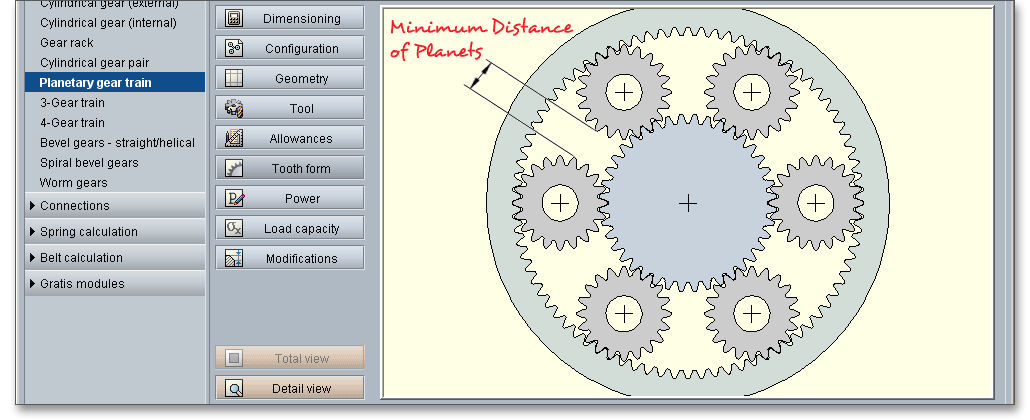
There are always several planet gears in the planetary gear train. The purpose of the planet gears is to share the tooth loads. This allows for a smaller module. Load sharing between the planet gears enables you to create a compact design, thus increasing the load capacity of the gear train. You can enter any number of planet gears you want. If the number of planet gears that are possible for the configuration is exceeded, a warning is shown in the message window. The calculation of the planetary gear train is then no longer possible.

Enter a minimum distance between the planet gears. The eAssistant software automatically checks the minimum distance. If the minimum distance cannot be obtained, you will get an information in the message window. It is preferable to use a symmetrical arrangement of the planet gears and if possible, the planet gears should be arranged uniformly over the circumference. The calculation module checks, if a symmetrical arrangement is possible and if the gear train can be mounted accurately. In case the symmetrical mounting is not possible, you will be notified in the message window. The necessary angle distribution is also displayed.
The normal module \(m_{n}\) is one of the basic parameters in the gear geometry and describes the size of a gear. The
module is defined as the ratio of the pitch diameter to the number of teeth of a gear. Note that the larger the
module the larger the teeth. The value of the module is defined in millimeters. In order to limit the number of the
gears, the module has been standardised in preferred series 1 and 2 (please see section 8.2.1 ‘Normal
module’). The calculation with the eAssistant software is possible with any modules including several decimal
places.
The most common pressure angle now in use for spur gears is \(20^{\circ }\). The default startup setting for the pressure
angle is set to \(20^{\circ }\). For special applications, the pressure angle can be defined individually and you can enter
another pressure angle than \(20^{\circ }\). Pressure angles above \(20^{\circ }\) give higher load capacity but may not run quite as
smoothly or quietly.
Use the listbox in order to define the motion state of the planetary gear train. There is usually one member
which is maintained in a fixed position. If you choose the entry ‘Planet carrier’, then the planetary carrier of the
gear train is held stationary. This is then a so-called stationary gear.
For spur gears the helix angle is \(\beta \) = \(0^{\circ }\), for helical gears the angle \(\beta \) is up to \(45^{\circ }\) due to the fact that the teeth for a helical gear are inclined by the angle. \(45^{\circ }\) is also the maximum value that you can enter into the input field for the helix angle.
The transmission ratio \(i\) (inner ratio) is determined by the number of teeth on each gear in the gear train. If
a deviation from a given transmission ratio, for example, is too large, then small changes in the
number of teeth are enough to adjust the transmission ratio without significantly increasing the
planetary gear train. In addition, the ratio is also dependent upon the motion state of the planetary gear
train.
Following the basic configuration of the planetary gear train, you can go on with the input of the geometry values. The calculation of the geometry is based on DIN standard, but with locking the input field for the tip circle diameter, tip diameter allowances and modification of tip diameter you can modify these values very easily. If you add profile shift and addendum chamfer, then these values are taken into consideration, too.
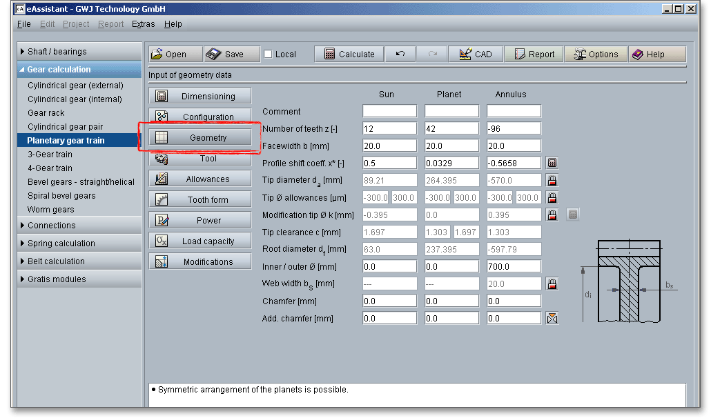
The facewidth \(b\) is the length of the gear teeth as measured along a line parallel to the gear axis. The facewidth
can be entered for the sun gear, planet gear and annulus gear.
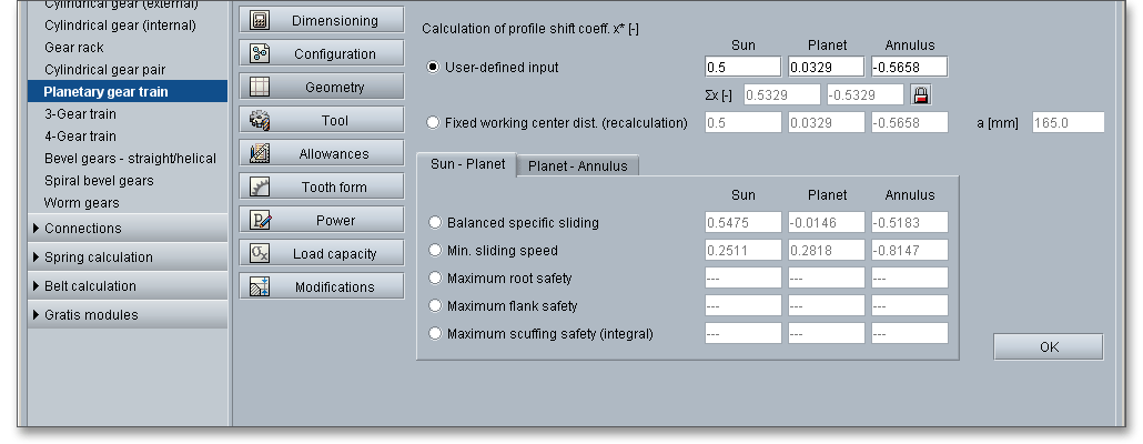
Profile shifting affects the gear tooth form and all properties of the gear because the tool is shifted by the value \(xm\) towards or away from the tip circle. The profile shift can make gears run more quietly and carry more load. It is used to avoid meshing interferences, to increase the load capacity and to improve the sliding conditions. The profile shift is distributed between the sun gear, planet gear and annulus gear and can be positive or negative. Profile shift is positive if the profile reference line is shifted from the reference circle towards the tip circle and negative if the profile reference line is shifted from the reference circle towards the root circle. A positive correction is effective to increase the load capacity of external gears and external gears usually have a positive profile shift. The positive profile shift may be disadvantageous for internal gears, thus internal gears get a negative profile shift. In order to optimize the profile shift coefficient, just click the ‘Calculator’ button.

In the calculation module, there are several options for optimizing the profile shift. Either enter your own values
for the profile shift coefficients or specify the profile shift sum to have the centre distance calculated
from it. For an optimal design, activate ‘Balanced specific sliding’ for the two pairings sun-planet or
planet-annulus. The balanced specific sliding is only possible for one pairing.Specific sliding is possible
only for one pairing. The factors are modified so that the specific sliding is balanced in order to
maximize wear resistance. The specific sliding has a positive effect on load capacity and low-noise
operation. Please note that the smaller the number of teeth the larger the influence of the profile
shift. If the values for the specific sliding are highlighted in red, then a dimensioning is not possible.
The sum of the profile shift coefficients is distributed equally between planet gear and annulus
gear.
The calculation module provides the function ‘Fixed working center distance (recalculation)’ for disconnecting
the profile shift sum and the center distance. With this function, the profile shift coefficients can be can be
specified independently of the center distance. This enables, for example, the calculation of existing gear pairs
that are to be installed in the housing with the ‘wrong’ centre distance. Transverse contact ratio, backlash and
load capacity are also calculated correctly in this case. This function can also be used for the calculation of
small-module gears.
Further options are available for the distribution of the profile shift coefficients: ‘Fixed working center distance (recalculation)’, ‘Minimum sliding speed’, ‘Geometric minimum gear 1’, ‘Geometric maximum gear 1’, ‘Maximum root safety’, ‘Maximum flank safety’ and ‘Maximum scuffing load capacity (integral)’. The last three options are only available for selection when the load capacity is activated.
For planetary gear trains, it is recommended to determine the profile shift according to conventional methods for external gearings (sun gear-planet gear) regardless of the internal gearing (annulus gear). Care must be taken to ensure that no meshing interferences occur. A large profile shift may cause meshing interferences, especially on the tooth root of the pinion. The calculation module warns as soon as meshing interferences occur. Please have a look at the sections 8.2.9 and 8.10.5 for cylindrical gears to get more information on profile shifting.
The tip diameter \(d_{a}\) depends on the module and will be determined by the program automatically. If you change the profile shift, the tip diameter will change, too. There is the possibility to enable the tip circle using the ‘Lock’ button. Now you can add and modify the tip diameter very easily. Please note that the tip diameter has an influence on the modification of the tip diameter. Click on the button again to disable the input field. The value is determined again according to DIN.

The tip diameter allowance is determined according to DIN. Click the ‘Lock’ button to enable the input field and enter your own value. If your values are out of range of the DIN, you will get an information in the message window. Click on the ‘Lock’ button and the input field is disabled again. The allowances are determined according to DIN.

The modification of the tip diameter \(k\) is automatically determined by the program that a sufficient tip clearance is available. For external gears the modification of the tip diameter is \(k \le 0\), for internal gears, the value is often set to \(k = 0\) in order to avoid meshing interferences. Click on the ‘Lock’ button to enable the input field and enter your own value. Such a modification of the tip diameter has an effect on the tip diameter.

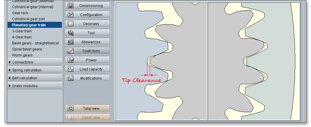
Clearance \(c\) is the distance between the root circle of a gear and the addendum circle of its mate. A certain clearance between the gears is necessary for a smooth operation without jamming.
The root diameter \(d_{f}\) depends upon the module, the profile shift and addendum coefficient of the basic rack profile.
The root diameter is determined by the program. Therefore, the root diameter occurs as a result of the
calculation.
Here you can enter an inner diameter (for sun gear and planet gear) and outer diameter (for annulus gear).
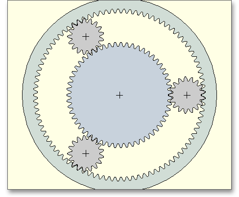
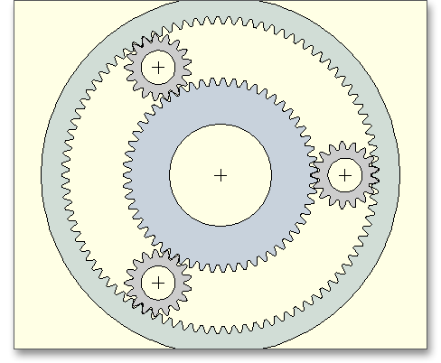
The web width can be considered here. The web width is shown in the figure next to the input field. There is the possibility to modify the web width by using the ‘Lock’ button.

Enter an inner diameter for sun gear and planet gear. The web width is first set to the same value as the facewidth. In case the web width is smaller than the facewidth, then the gear body stiffness is affected due to the gear body coefficient \(C_{R}\). The tooth spring stiffness changes which affects again the load capacity. By clicking on the ‘Lock’ button, you can define the web width.

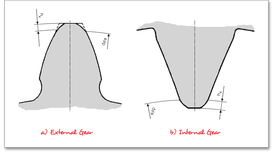
The tooth ends of a gear are often rounded or chamfered. The chamfer and addendum chamfer can be considered for sun gear, planet gear and annulus gear. An addendum chamfer is a small angled surface added on the end of a shaft along an edge. Meshing interferences can be removed by the addendum chamfer. The chamfer reduces the calculated tooth width when calculating the load capacity of the tooth root and flank. As an alternative to the addendum chamfer, a tip corner radius can be specified. This can be defined either as a radial amount or directly as a radius.
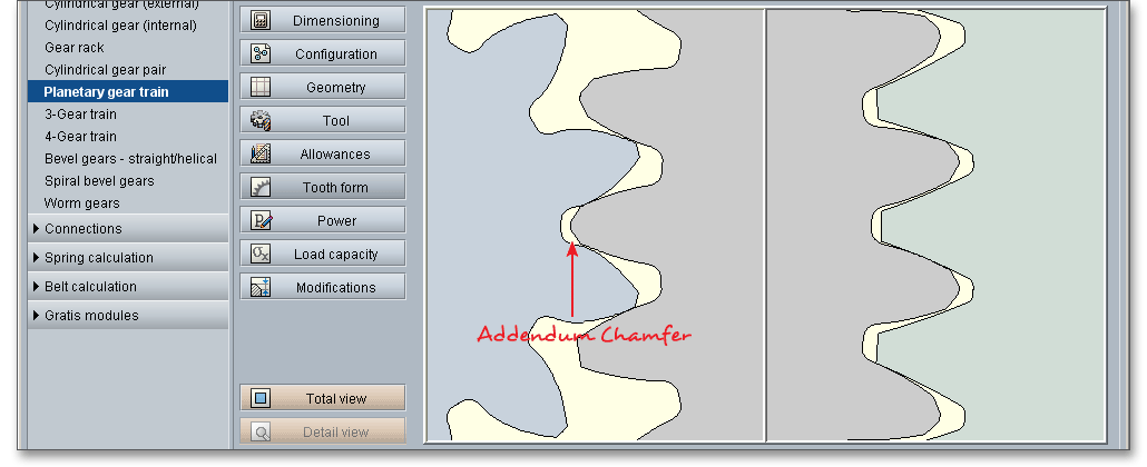
The selection is marked by the colored arrow. The radius is entered directly for the tip radius, the radial amount is entered for the tip radius (Rad.). If you enter the tip radius directly as a value, you will receive the corresponding radial amount in the calculation report.
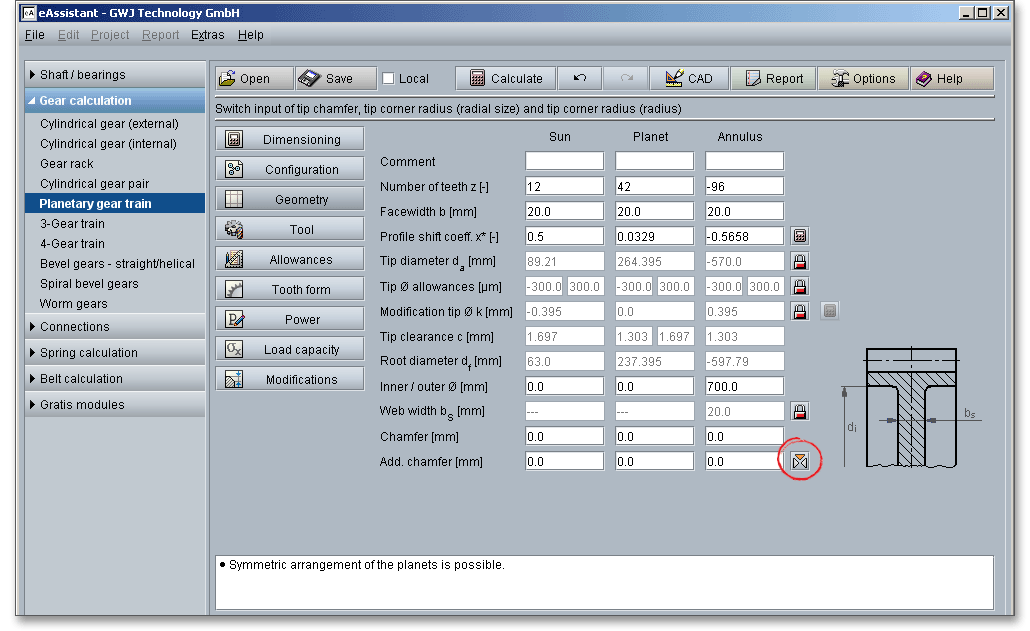
In the case of tip corner radius or addendum chamfer, the tip form diameter is smaller than the tip circle diameter by twice the radial amount \(h_{K}\).
Here, you can choose the type of tool for the sun gear, planet gear and annulus gear. A basic rack profile according to ISO 53, DIN 867 and DIN 3972 can be selected from a listbox or can be defined individually. A machining allowance can be taken into consideration.
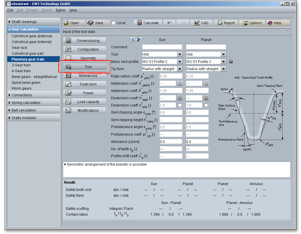
You can use the arrow to quickly toggle between the gear pairing sun gear-planet gear or planet gear-annulus gear.

Please note: You can add a description or a short comment to sun gear, planet gear and annulus gear. The
notes will appear later in the calculation report.
The most important manufacturing processes are gear hobbing and gear shaping. Select either the tool ‘Hob’ or ‘Gear shaper cutter’ by clicking the listbox. A ‘Constructed involute’ is also available. Basically, the selection of the tool depends on the gear type (external or internal gears). The external gears can be produced by cutting wherein the gear cutting tool is a hob. For internal gears a gear shaper cutter is used.

The hobbing is the most widely used method of cutting gear teeth. The hobbing process is quite advantageous in cutting gears with very wide facewidth. A very high degree of tooth-spacing accuracy can be obtained with hobbing. With regard to accuracy, hobbing is superior to the other cutting processes. A wide variety of sizes and kinds of hobbing machines are used. The rotating hob has a series of rack teeth arranged in a spiral around the outside of a cylinder, so it cuts several gear teeth at one time.
Normally internal gears are manufactured by gear shaping method. The shaping process is a gear-cutting method in which the cutting tool is shaped like a pinion. If a gear is provided with cutting clearance and is hardened, it may be used as a generating tool in a gear shaper. The cutter reciprocates while it and the gear blank are rotated together at the angular-velocity ratio corresponding to the number of teeth on the cutter and the gear.
In addition to the hob and the gear shaper cutter, you can also select the entry ‘Constructed involute’ as a
tool. In case internal gears cannot be shaped with a gear shaper cutter, the tooth form calculation
is still possible by using the constructed involute. This specifically applies for applications in the
precision mechanics. This method allows a generation of the tooth form with a constant root fillet
radius.
Please note: Please take a look at the figure in section 8.3.1 to see the hob and the shaper and also to get
more information.
The standard basic rack tooth profile is standardized in DIN 867. The tool standard basic rack profile is the counter profile of the standard basic rack tooth profile. The following standard basic rack profiles are available for your calculation. Choose your profile from the listbox.

In addition to the standard basic rack profiles, you can also select a protuberance tool. When part of the involute profile of a gear tooth is cut away near its base, the tooth is said to be undercut. By using a protuberance tool an undercut near the root can be generated. Grinding notches at the tooth flank can be avoided during the grinding.

You can select the following profiles:
Please note: If you select ‘user defined input’, then the input fields for the edge radius, the addendum
coefficient and the dedendum coefficient are activated. Now you can modify the basic rack profile.
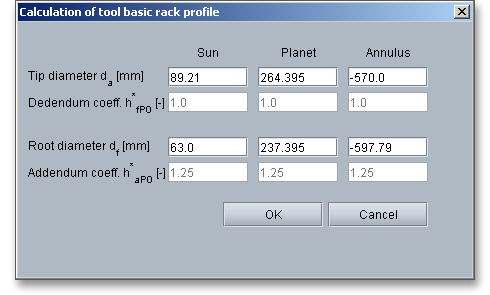
In case you use special tools, the eAssistant software offers an easy and comfortable solution. As mentioned above, the basic rack profile can be specified by the entry ‘user defined input’.

Here you can change the tip circle and the root diameter for sun gear, planet gear and annulus gear. Confirm your entries with the button ‘OK’. The listbox for the basic rack profiles displays then ‘user defined input’. The modification of tip is set to ‘0’.
For the tip form you can choose between ‘Full radius’ and ‘Radius with straight line’. Normally ‘Radius with
straight line’ is used.
eAssistant provides a functionality for tools with a shifted profile reference line. Additionally to the addendum
coefficient \(h^{*}_{aMP0}\) of the shifted profile, the dedendum coefficient \(h^{*}_{fMP0}\) is displayed and visible in the calculation report. The
dedendum coefficient \(h^{*}_{fMP0}\) can also be defined by clicking the ‘Lock’ button so that the dedendum coefficient \(h^{*}_{fP0}\) of the
converted, non-shifted basic rack profile is always 1.0 according to DIN 867. Section 8.3.4 shows an
illustration.
With the definition of the semi topping flank, corresponding hobs can then be specified. These generate an
addendum chamfer during the cutting process. The option ‘Topping’ allows to define the tip diameter directly
with the dedendum coefficient of the tool, making it impossible to subsequently modifiying the tip
diameter. The result, at the same time, will be tip diameter allowances analogous to the root diameter
allowances directly from the tooth thickness allowances. The eAssistant 3D CAD plugins for various
CAD systems support the function and the semi topping flank can be considered in the 3D CAD
model.
Undercut may be deliberately introduced to facilitate finishing operations. Undercut is the loss of profile in the vicinity of involute start at the base circle due to tool cutter action in generating teeth with low numbers of teeth. The protuberance cuts an undercut at the root of the gear tooth. The protuberance design is also used in some cases to permit the sides of gear teeth to be ground without having to grind the root fillet.
To avoid grinding steps, a deviation in the tooth root area of the profile is a common and allowed method. Because of a grinding stock allowance, an undercut must be allowed. Hence, a larger tooth root thickness is necessary. The following table shows some determination of the undercut dependent upon the module.
| Undercut \(s_{pr}\) for Ground Gears Dependent upon Module1
| |||||
| Module | Allowance | Size of | Protuberance | Addendum | Edge Radius |
| \(m\) | \(q\) | Undercut \(s_{pr}\) | \(pr^{*}_{P0}\) | \(h^{*}_{aP0}\) | \(\rho ^{*}_{aP0}\) |
| 2 | 0,160 | 0,100 | 0,260 | 2,900 | 0,500 |
| 2,5 | 0,170 | 0,110 | 0,280 | 3,625 | 0,625 |
| 3 | 0,180 | 0,120 | 0,300 | 4,350 | 0,750 |
| 4 | 0,200 | 0,140 | 0,340 | 5,800 | 1,000 |
| 5 | 0,220 | 0,160 | 0,380 | 7,250 | 1,250 |
| 6 | 0,240 | 0,180 | 0,420 | 8,700 | 1,500 |
| 7 | 0,260 | 0,200 | 0,460 | 10,150 | 1,7500 |
| 1 from: Linke, H.: Stirnradverzahnung Berechnung Werkstoffe Fertigung, Carl Hanser
Verlag, Muenchen, Wien, 2nd ed. 2010, p. 68, table 2.1/2
| |||||
You can consider an allowance for the tooth flank. The tool provides an allowance \(q\) on the flank and/or root for the pre-cutting tool. The allowance is the smallest distance between the involutes and the pre-machining having the same root diameter.
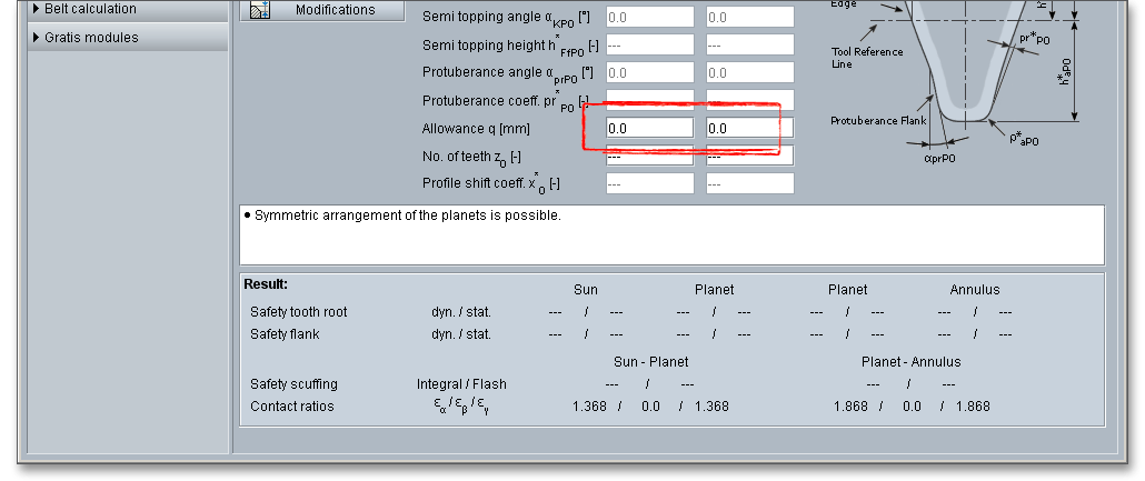
In case you select the tool basic rack profile with protuberance, the allowance refers to the tooth flank. If the allowance of the tool basic rack profile is selected without protuberance, then tooth flank and tooth root get the allowance. The maximum machining allowance can be classified as follows:
| Maximum Machining Allowances2
| |
| Allowance per Tooth Flank | Manufacturing Process |
| \(<\) 0.05 (0.10) mm | Finishing operation by cold rolling, gear shaving, honing, lapping |
| 0.05 to 0.5 (1.5) mm | Grinding, profile grinding, (honing) |
| \(>\) 0.5 mm, pre-cutting | Primary shaping, forming, cutting with geometrically determined edges except shaving, grinding and profile grinding in special cases |
| 2 from: Linke, H.: Stirnradverzahnung Berechnung Werkstoffe Fertigung, Carl Hanser
Verlag, Muenchen, Wien, 1996, p. 638
| |
Please note: Please see section 8.3.6 and 8.3.7 to get more information on protuberance and machining
allowance.
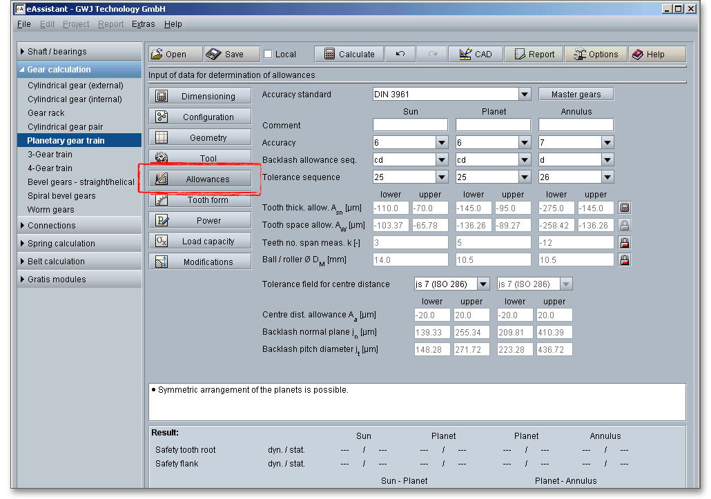
This input mask allows to define the gear quality and the tolerance for the sun gear, planet gear and annulus gear. In addition, the program determines the upper and lower tooth thickness and tooth space allowances. The tooth thickness can be defined individually as well. The required number of teeth for the span measurement and the ball/roller diameter will be calculated or can be also defined manually. A manufacturing of work-pieces with accurate nominal dimensions is impossible. Hence, a deviation from the nominal size has to be allowed. For a lot of applications the gear and the pinion of a pair must be independently manufactured and meshed without any modifications. That means, the parts have to be separately replaceable. In addition to DIN 3961 for gear tolerances/gear qualities, DIN 58405 for precision engineering as well as ISO 1328 and ANSI/AGMA 2015 are available.
Please note: You can add a description or a short comment to sun gear, planet gear and annulus gear. The
notes will appear later in the calculation report.
The choice of the right toothing quality is determined by economical aspects depending upon the intended purpose and manufacturing process. In all fields of gearing, the control of gear accuracy is essential. Several classes or grades of accuracy can be set. 12 grades (12 to 1) are defined according to DIN standards. High accuracy grades can be set for a long-life, high speed gears. Lower accuracy grades will cover medium- or slow-speed grades. Accuracy grade ‘1’ describes the highest possible accuracy, ‘12’ a very low accuracy. The gear accuracy ‘1 to 4’ is mainly used for master gears, quality ‘5 to 12’ is used for gear wheels. Section 8.4.1 provides an overview of manufacturing process depending on the gear quality. You can also find a table with reference values for the selection of the quality and tolerances. The gear quality can be selected from the listbox for the sun gear, planet gear and annulus gear.
For the gear tolerances/gear qualities, DIN 58405 for precision engineering as well as ISO 1328 and
ANSI/AGMA 2015 are also available. For ISO 1328 and ANSI/AGMA 2015, two qualities can be selected in each
case. The first quality is comparable with the tolerances permitted according to DIN 3961, the second value
influences the radial composite deviation as well as the roll deviations.
The system for gearings is very similar to the DIN system of fits and tolerances. For the system of fits for gear transmissions letters are used to indicate the deviation from basic (nominal) size, a number defines the width. There are clearance fits for gearings, therefore, lower case characters ‘h’ to ‘a’ appear. If you select the entry ‘user defined input’, the input field for the tooth thickness allowances is enabled and you can define your individual values.
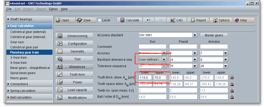
One of the most important criteria of gear quality is the specification and control of tooth thickness. The magnitude of tooth thickness and its tolerance is a direct measure of backlash when the gear is assembled with its mate. Dimensional changes, due to thermal expansion, do not allow a zero-backlash assembly. The tooth thickness allowance has to be determined that no jamming occurs. To prevent that jamming of gears during the operation, it is necessary to decrease tooth thickness by a minimum amount (\(A_{sne}\) and \(A_{sn}\)). Click the ‘Calculator’ button in order to determine the tooth thickness allowances from measured data or given test dimensions.

A new window is opened.
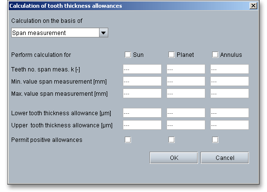
Activate sun gear, planet gear and annulus gear and enter the input values. Confirm with the button ‘OK’. The
‘Lock’ button next to the input field for the tooth space allowances is enabled. Now you can change the tooth
space allowances.
The tooth space allowance \(A_{W}\) is the difference between the actual dimension and the nominal dimension of the span measurement \(W{_k}\). The actual measurement of the span measurement gets smaller for external gears by negative allowances for a zero-backlash assembly. The upper and lower tooth space allowance are displayed as well. For an own input of the tooth thickness allowances, the tooth space allowances can be defined as well. The ‘Lock’ button next to the input field of the tooth space allowances is enabled. Therefore, you can change the tooth space allowances.

The tooth thickness of a gear may be measured directly with calipers or it may be determined indirectly by diameter pins. The sizing of gears may be controlled by double-flank composite checks and centre distance settings corresponding to maximum and minimum tooth thickness specifications. Different measurement methods are used:
Span measurement \(W_{k}\) is the measurement of the distance across several teeth in a normal plane. As long as the measuring device has parallel measuring surfaces that contact on an unmodified portion of the involute, the measurement will be along a line tangent to the base cylinder. It is a widely used method for gauging the tooth thickness by using the span measurement. The tooth thickness of spur or helical gears is often measured with calipers. An advantage is that the dimensions can be influenced during the manufacturing. The calculation program determines the number of teeth for the span measurement (number of teeth across the span measurement has to be gauged). By using the ‘Lock’ button you are able to activate the input field and you can enter your own input value. If you click the button again, the previous input value appears.

The tooth thickness is often checked by measurement over pins \(M_{dR}\) or balls \(M_{dK}\). The pins or balls are placed in diametrically opposed tooth spaces (even number of teeth) or nearest to it (odd number of teeth). Measurement over pins is the measurement of the distance taken over a pin positioned in a tooth space and a reference surface. The reference surface may be the reference axis of the gear, a datum surface or either one or two pins positioned in the tooth space or spaces opposite the first. The measurement over pins is only used for spur gears and external helical gears. For the measurement values a distinction is made between:
For an external gear the measurement over balls \(M_{dK}\) is the largest outer measure. The two balls are placed in diametrically opposed tooth spaces. The balls have to be in the same plane perpendicular to a gear axis. For an internal gear (see figure: ‘Internal spur gear with odd number of teeth’) the measurement over balls is the smallest inner measure between the balls. \(D_{M}\) is the diameter of ball or pin. The internal gear is generally checked for tooth thickness with measuring pins, like the external gear. However, the measurement is made between the pins instead of over pins.

Please note: Please see section 8.4.5 for figures of the span measurement and tooth thickness
measurement.
The general purpose of backlash is to prevent gears from jamming and making contact on both sides of their teeth simultaneously. The center distance and the gear fits have an important influence on the backlash. The gear fit selection defines the tolerances of the centre distance with the backlash. The gear fit selection provides only one tolerance field. The allowances are indicated for the ‘JS’ field. These conform to the ISO basic tolerances. The backlash is dependent upon the tooth thickness allowances, the tooth space allowances and the centre distance. Hence, if you change the centre distance, then the backlash is changed, too.

Select the option ‘user defined input’ from the listbox. Now you are able to enter your own centre
distance allowances. Confirm your entries with the Enter key. The backlashes are automatically
determined.
The centre distance allowance \(A_{a}\) is the allowed deviation of the centre distance from the nominal centre distance.
The allowances are indicated with \(\pm \) to get no improper major allowances from the nominal centre distances with
gears having several axes.
A gear fit has to be determined, so that two gears can be meshed. For that, a proper backlash must be provided for the mesh to avoid jamming of the gears. The eAssistant software offers three different backlashes:
The backlash pitch diameter \(j_{t}\) refers to the backlash at the pitch circle. The backlash pitch diameter may be the length of the pitch circle arc in which the gear rotate against its mating gear. The radial backlash is the difference of the centre distance between the working condition and zero-backlash engagement. The radial backlash \(j_{r}\) matters especially for very small modules (m \(<\) 0.6 mm). Section 8.4.7 illustrates the different backlashes.
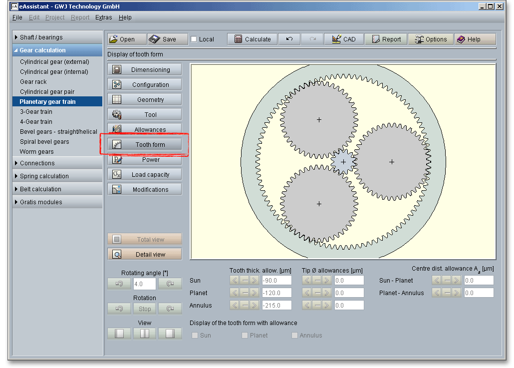
A special highlight of this calculation module is the presentation of the accurate gear tooth form with an animation and simulation of the tooth mesh of the pairings sun gear-planet gear and planet gear-annulus gear. For the presentation you can select the lower, upper and mean allowances for the tooth thickness, tip diameter and centre distance.
Please note: Please keep in mind that all values are later taken over to the DXF output and CAD generation. In
case you change the tooth thickness allowance or the centre distance allowance in the tooth form mask, then
the last modification is taken over to the DXF output. The section 9.20 ‘CAD button’ contains some helpful
information on this function.

Click on the ‘Tooth form’ button to represent the planetary gear train.
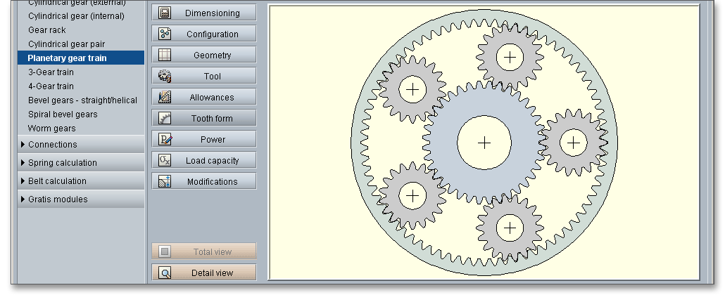
Click on the ‘Detail view’ button. You get a larger representation of the gear tooth mesh of the pairing sun gear-planet gear and planet gear-annulus gear. Now you can see the detailed tooth mesh. The representation of the tooth mesh allows you to look at the tooth thickness allowances, the tip diameter and centre distance allowances as well the tooth mesh and to check the influence of these values. The tooth form mask provides various functions. Click on the ‘Total view’ button to obtain an entire view of the planetary gear train.
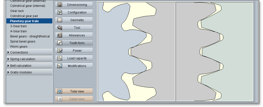
Click the button ‘Detail view’, the gear mesh of sun gear-planet gear and planet gear-annulus gear is displayed. Each gear tooth mesh (i.e., sun gear-planet gear or planet gear-annulus gear) can be also be displayed individually (see 9.7.5 ‘View’).
Enter an rotating angle for the rotation of the gear pair.

|
| Rotation of the driving gear counter-clockwise |
|
| Rotation of the driving gear clockwise |
When you click on one of the two arrows, a continuous rotation of the gears occurs.

|
| Continuous rotation of the driving gear counter-clockwise |
|
| Continuous rotation of the driving gear clockwise |
|
| The rotation is stopped. |
There are two ways to view the mesh: The tooth mesh of sun gear-planet gear and planet gear-annulus gear can be displayed side by side or individually where you can see either the tooth mesh of sun gear-planet gear or planet gear-annulus gear. The tooth mesh of each pairing can be viewed closer by clicking ‘Rotation’ or ‘Rotating angle’.

|
| Show only tooth mesh of sun gear and planet gear. |
|
| Show tooth mesh of both pairings sun gear-planet gear and planet gear-annulus gear. |
|
| Show only tooth mesh of planet gear and annulus gear. |
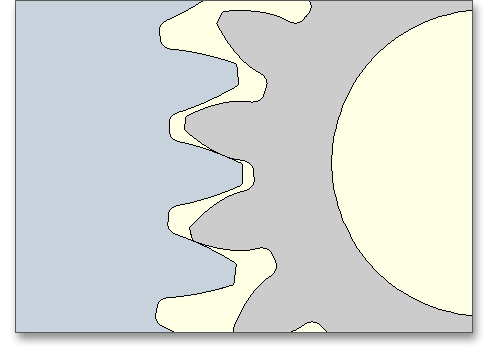
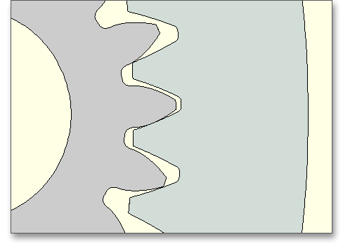
Click on the ‘Detail view’ button and the tooth mesh is represented in detail. Now you can change the tooth thickness allowance, that is already given in the main mask for the ‘Allowances’, within the tolerance limit. All changes are displayed immediately. For the representation of the tooth mesh, select the lower, upper and mean tooth thickness allowances for sun gear, planet gear and annulus gear.

Both arrows indicate the lower and upper allowance. The active input is grayed out and disabled. Click on the left arrow and you will get the representation for the lower tooth thickness allowance. The right arrow shows the representation for the upper tooth thickness allowance. The middle button displays the mean tooth thickness allowance. At the first start of the tooth form, you will get the mean tooth thickness allowance. The tooth thickness allowances can be defined between the lower and upper allowance.

Please note: In case you have specified the lower and upper tooth thickness allowance for sun gear, planet
gear and annulus gear in the input mask ‘Allowances’ by using the calculator button, then the manually defined
values appear here as lower and upper tooth thickness allowance.
Click the ‘Detail view’ button and the tooth mesh is represented in detail. Now you can change the tip diameter allowance, that is already given in the main mask for the ‘Geometry’, within the tolerance limit. All changes are displayed immediately. For the representation of the tooth mesh, select the lower, upper and mean tip diameter allowances for sun gear, planet gear and annulus gear.

Both arrows indicate the lower and upper allowance. The active input is grayed out and disabled. Click on the left arrow and you will get the representation for the lower tip diameter allowance. The right arrow shows the representation for the upper tip diameter allowance. The middle button displays the mean tip diameter allowance. At the first start of the tooth form, you will get the mean tip diameter allowance. The tip diameter allowances can be defined between the lower and upper allowance.

Please note: In case you have specified the lower and upper tip diameter allowance for sun gear, planet gear
and annulus gear in the input mask ‘Geometry’ by using the ‘Lock’ button, then the manually defined values
appear here as lower and upper tip diameter allowance.
Click on the ‘Detail view’ button and the tooth mesh is represented in detail. Now you can change the centre distance allowance, that is already given in the main mask for the ‘Allowances’, within the tolerance limit. All changes are displayed immediately. You can check the operation of the gears by using various centre distance settings. For the representation of the tooth mesh, select the lower, upper and mean centre distance allowances for sun gear, planet gear and annulus gear.

Both arrows indicate the lower and upper allowance. The active input is grayed out and disabled. Click on the left arrow and you will get the representation for the lower centre distance allowance. The right arrow shows the representation for the upper centre distance allowance. The middle button displays the mean centre distance allowance. At the first start of the tooth form, you will get the mean centre distance allowance. The centre distance allowances can be defined between the lower and upper allowance.

Please note: In case you have specified the lower and upper centre distance allowance in the input mask
‘Allowances’ by using the ‘User defined input’ option, then the manually defined values appear here as lower
and upper centre distance allowance.
In addition to the geometry calculation, torque, speed including the relative speed of the planet as well as the power, pitch power and coupling power will be determined. Tangential force of the planet carrier and the centrifugal force of the planet are calculated as well. You can find both values in the calculation report. The main advantage of planetary gear trains is that the gear tooth forces are distributed among several planets, thus increasing the load capacity of the gear train. Planetary gear trains can easily achieve larger transmission ratio as well as higher torques. In the ideal case, the circumferential forces are distributed uniformly on the tooth mesh of the planets. Forces and torques are transmitted by means of axes and shafts. The planet gears of the gear train can be mounted on the axis or on a shaft.
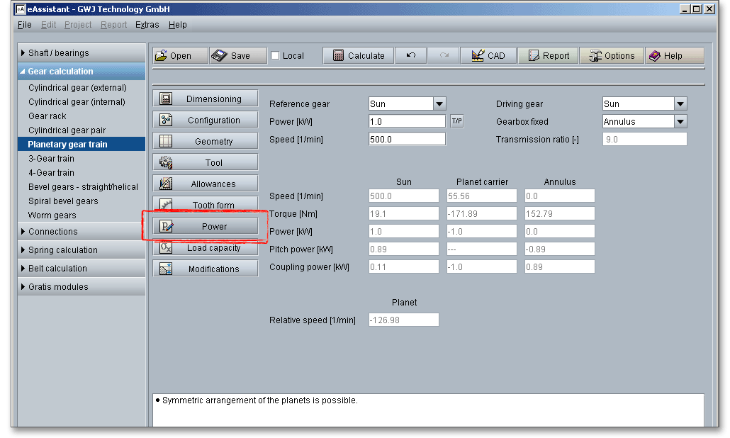
Click on the adjacent ‘T/P’ button to toggle between the input for the torque and the input for the power. If you click on the ‘TP’ button, then you can enter either the torque or the power. The values are converted. The description of the input field changes accordingly into ‘Torque’ or ‘Power’. There are three torques acting on the planetary gear train. According to the principle of conservation of energy, the sum of all torques must equal zero. The torques have positive and negative signs. Two of the three torques always have the same sign. If one torque is given, then the other torques are automatically determined.

The input power \(P_{A}\) is always positive and the output power is always negative. Torque and speed have the same sign for an input shaft but opposite signs for an output shaft. The external power ‘flows’ from the input shaft to the output shaft.

In a planetary gear train a difference is made between shaft power, pitch power and coupling power. The pitch
power \(P_{W}\), the product of circumferential force \(F_{u}\) at pitch circle and sliding velocity, is an internal power. The power
is transmitted when the gears are in mesh and rotate. If the planetary carrier is locked, the total
power \(P\) is transmitted as pitch power by the gears. Then the pitch power \(P_{W}\) is equal to the shaft power \(P\)
transmitted by the connected shafts. For a gear train with a revolving carrier, the pitch power \(P_{W}\) is
not equal to the shaft power \(P\). Shaft power and pitch power differ by the amount of the coupling
power.
Please note: The pitch power causes tooth friction losses. The amount of the pitch power in the power
transmission should be kept as small as possible. The lower the pitch power, the better the gear
efficiency.
Planetary gear trains transmit the external shaft power \(P\) as pitch power \(P_W\) and coupling power \(P_{k}\). The coupling power is transmitted without loss.
Speeds relative to the stationary gear housing are known as absolute speeds. The speed relative to the shaft is
called relative speed.
The calculation of load capacity of cylindrical gears is standardized according to DIN 3990, ISO 6336 (2006, 2019), ANSI/AGMA 2101-D04 as well as VDI 2736 for plastic gears. The standards give different methods to calculate the load capacity in DIN 3990, ISO 6336 and ANSI/AGMA 2101-D04. The eAssistant software provides all calculations according to DIN 3990 Method B, ISO 6336 Method B, ANSI/AGMA 2101-D04 and VDI 2736.
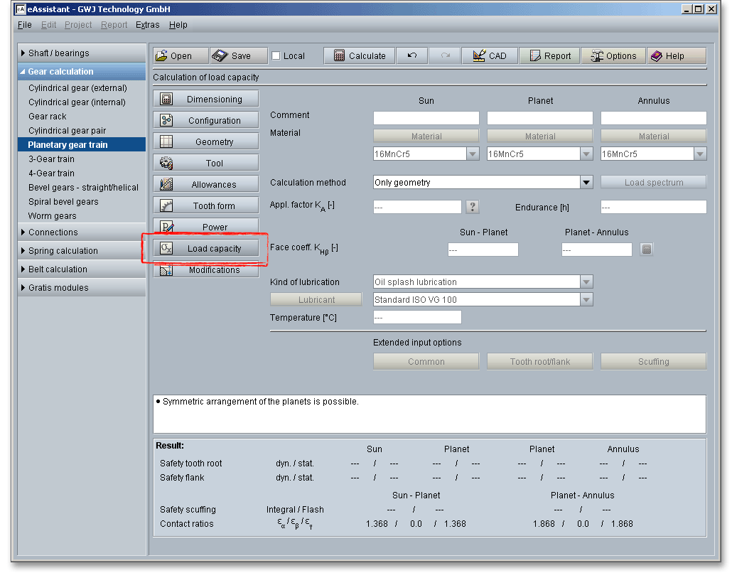
For planetary gear trains, the uneven load distribution of the planet gears must also be taken into consideration. Gears fail by tooth breakage, pitting as well as by scuffing. The strength is determined by the loads, the geometry of gearing as well as selected materials. The calculation of the load capacity is about the proof of the following strength factors that result from the above-mentioned forms of damage:
You can check the load capacity of tooth root and tooth flank as well as the scuffing fast and easily. The scuffing
safeties are determined according to the integral and flash temperature method. The material properties, the
endurance, face load factor, application factor as well as the kind of lubrication and the selected lubrication are
taken into consideration for the calculation. There are extended input options to influence the number of load
changes or the roughness. A grinding notch can be integrated into the calculation and the mode of operation
can be selected.
The following factors consider the influences of the load capacity calculation:
Tooth breakage is a fatigue failure. Pitting, scuffing or wear may weaken the tooth so that it breaks. The slow
progress of the fracture apparently causes the metal to break like brittle material. A tear or grinding notch may
cause a tooth breakage. Gear tooth fractures ordinarily start in the root fillet. The tooth breakage can destroy an
entire gearing and leads to a failure of the gearing. Sometimes a new tooth will break as a result of severe
overload or a serious defect in the tooth structure. According to DIN 3990, an operation with a reduced load is
possible after a tooth breakage, if just a small portion of a tooth broke off and the other parts of the gearing are
intact.
For a high load capacity of the tooth root, the following methods are advantageous: positive profile shift (for
small number of teeth), usage of hardened and tempered or case-hardened materials with larger load capacity
of the tooth root, larger root fillet, larger module
Pitting is a fatigue failure and is characterized by little bits of metal breaking out of the surface and thereby
leaving small holes or pits, so that oil seeps into the pits. This is caused by high tooth loads leading to excessive
surface stress, a high local temperature due to high rubbing speeds or inadequate lubrication. The
cracking of the surface develops, spreads and ultimately results in small bits breaking out of the tooth
surface. But it is often possible to get some years of service out of gears that have pitted rather
extensively.
For a high load capacity of the tooth flank, the following methods are advantageous: large number of teeth,
positive profile shift (for small number of teeth), higher pressure angle, large hardness of tooth flank, nitriding,
more viscous oil
Scuffing is a surface destruction and it can be caused by a lubrication failure. Tears and scratches appear on the rubbing surface of the teeth. This form of damage is called ‘scuffing’. The terms of ‘scuffing’ and ‘scoring’ are used interchangeably. Scuffing is an important form of damage leading to component replacements in lubricated mechanical systems. Compared with tooth breakage and pitting, it is not a fatigue failure, it can come very quickly. A short overload can lead to scuffing and the gearing fails. Scuffing is apt to occur when the gears are first put into operation because the teeth have not sufficient operating time to develop smooth surfaces. Due to the scuffing, the temperature, the forces and the noise increase, the gear teeth finally break off. The following factors may influence the occurrence of scuffing:
After the occurrence of scuffing, high-speed gears apt to additional dynamic forces that cause usually pitting or tooth breakage. The high surface temperature may cause a breakdown of the lubricating film. The following factors support scuffing:
For a high scuffing load capacity, the following methods are advantageous: E.P. oils (oil that contains chemical
additives), a careful running-in period of the gearing, low sliding velocity due to tip relief and a smaller
module
Click on the ‘Load capacity’ button to get to the calculation mask. You will notice that all input fields or listboxes are disabled. When you select the entry ‘DIN 3990 Method B’, ‘ISO 6336 Method B (2006, 2019)’, ‘ANSI/AGMA 2101-D04’ or ‘VDI 2736’ from the listbox ‘Calculation method’, all input fields are enabled. In case you do not need the calculation for load capacity, the calculation can be disabled. Thus, the size of the calculation report becomes smaller.
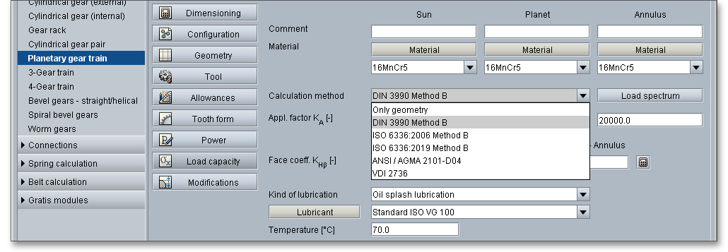
You can add a description or a short comment to sun gear, planet gear and annulus gear. The notes will appear later in the calculation report.
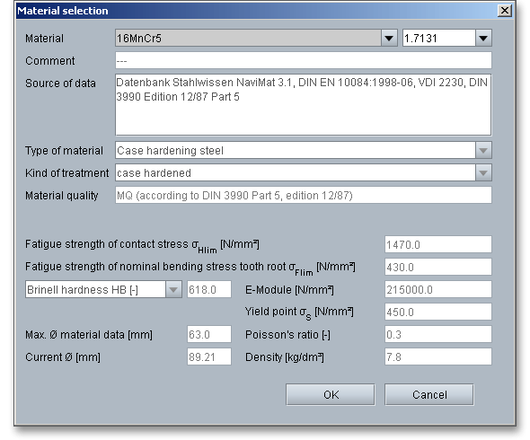
Select an appropriate material directly from the listbox for the sun gear, planet gear and annulus gear or click on the button ‘Material’ to open the material database.

The material database provides some detailed information on the several kinds of material. If the listbox is active, the two arrow keys ‘Up’ and ‘Down’ of your keyboard allows you to search through the database, so you can compare the different values with each other.
In order for gears to achieve their intended performance, life and reliability, the selection of a suitable material is
very important. Steel is the most common material that is used for gears. There are a number of steels used for
gears, ranging from plain carbon steels through the highly alloyed steels from low to high carbon
contents. The choice will depend upon a number of factors, including size, service and design.
For pinion and gear, the same hardened and tempered steel may be used. It has to be kept in
mind that unhardened gears with equal hardness should not be meshed with each other because
scuffing is apt to occur. A hardened or nidrided gear \(HRC > 50\) smoothes the tooth flanks of the hardened and
tempered mating gear, reduces the form deviations and increases the load capacity of the tooth
flank. For a mating of hardened gears, no hardness difference is necessary. The final selection of
the material should be based upon an understanding of the material properties and application
requirements.
Steel casting: Steel casting belongs to the ferrous metals that include carbon (up to max. 2%) and are
poured into sand molds to produce several components. Due to a higher melting temperature,
steel casting is more difficult to cast than cast iron. Steel casting is cheaper than ground or forged
gears.
Steel: Steel is the most common material and is used for medium and high-loaded gears.
Nidrided steel: Nitriding is adding nitrogen to solid iron-base alloys by heating the steel in contact with
ammonia gas or other suitable nitrogenous material. This process is used to harden the surface of
gears.
Case-hardened steel: Case-hardened steel is a quality and high-grade steel with low carbon content.
Case-hardened steel is usually formed by diffusing carbon (carburization), nitrogen (nitriding) into the outer layer
of the steel at high temperature and then heat treating the surface layer to the desired hardness. When the steel
is cooled rapidly by quenching, the higher carbon content on the outer surface becomes hard while the core
remains soft and tough.
Blackheart malleable cast iron (pearlitic structure): Malleable cast iron is a heat-treated iron carbon alloy. Two
groups of malleable cast iron are specified, whiteheart and blackheart cast iron. Blackheart malleable cast iron
is used for parts with a complex shape, in which a high durability, shock resistance and good machining are
important. Malleable cast iron is used for smaller dimensions and has got a higher strength and toughness than
steel castings.
Cast iron with spheroidal graphite (pearlitic structure, bainitic structure, ferritic structure): Cast iron usually refers
to gray cast iron but identifies a large group of ferrous alloys that contain more than 2% of carbon. It is extremely
rare that the maximum carbon content is higher than 4.5%. Cast iron is a low-priced material. However, cast iron
has less toughness and ductility than steel. Cast iron with spheroidal graphite can be used for parts with higher
vibration stress.
Heat-treated steel: Hardening and tempering is a heat-treating technique for steels by quenching from the
hardness temperature and annealing at a high temperature so that the toughness is increased significantly. At
the same time, a higher elastic limit is reached. Annealing temperatures and times differ for different
materials and with properties desired, steel is usually held for several hours at about \(400^{\circ }\)C to \(700^{\circ }\)C. Some
steels have to be cooled very quickly (Annealing: in order to achieve the intended properties of work
pieces (e.g., desired strength or toughness), reheating of the work pieces to certain temperatures is
necessary.).
Gray cast iron: Gray cast iron is used for complex shapes and offers low cost and an easy machinability. It
provides excellent damping properties but it is a disadvantage that the load capacity is very low.
In case there is no material that will fulfill the design requirements, then simply define your individual material. Select the option ‘User defined input’ and all inputs and options are activated and you can specify your individual material very easily. Your inputs will be saved to the calculation file. Please be advised that changing the material will delete your defined inputs and you have to enter the inputs again.
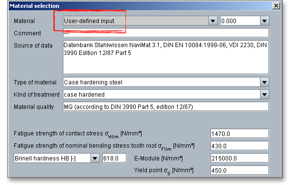
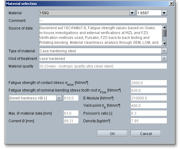
Ovako´s clean steels 159X and 159Q can be selected from the listbox. Both steels are based on the case-hardening steel 18CrNiMo7-6. Due to significantly lower levels of contamination, these steels have modified Woehler curves. Within the static strength, both steels are comparable to 18CrNiMo7-6. However, in the fatigue strength range the IQ-Steel 159Q (Isotropic Quality ultra clean steel) is designed to increase efficiency by 30 percent for the flank load capacity and 60 percent for the tooth root load capacity. The fatigue strength values are based on Ovako´s in-house investigations and external verifications at WZL of RWTH Aachen University and at the Gear Research Centre (FZG) of Technical University of Munich.
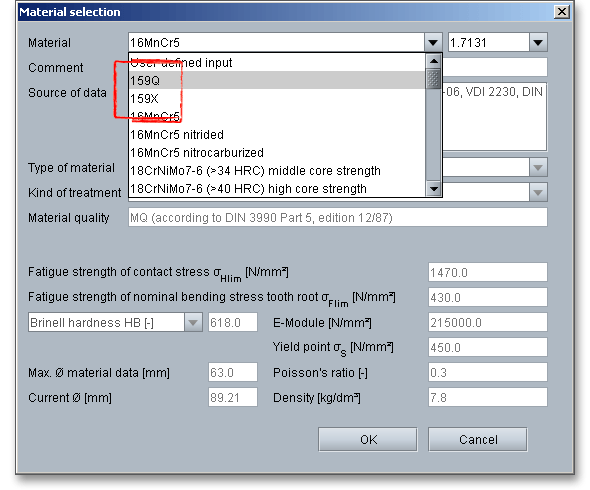
The BQ-Steel 159X (Bearing Quality clean steel) delivers slightly smaller performance gains compared to 18CrNiMo7-6 and can be taken to improve existing designs. The potential of the 159Q can be used particularly in new designs. It can be advantageous to focus on optimized scuffing load capacity. This can be achieved by increasing the number of teeth and simultaneously reducing the module. This generally results in better gear efficiency and lower power losses. These Ovako steels open up completely new design possibilities for gears and have a high potential for further increasing the performance of gears and gear components.
The calculation of load spectra is in accordance with ISO 6336, Part 6. The determination is based on the Palmgren-Miner rule and the load-dependent K-factors are calculated for each torque class. The safeties are determined by way of iteration until the sum of damage parts is obtained. This method, demanded by the wind energy industry, is very accurate. The linear damage accumulation model, which is also known as Palmgren-Miner’s rule, defines damage as the ratio of the number of cycles of operation to the number of cycles to failure at any given stress level.
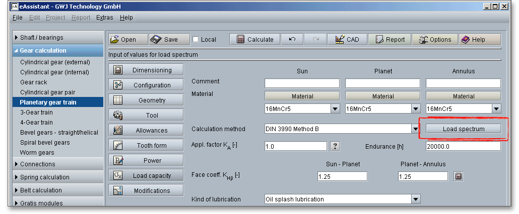
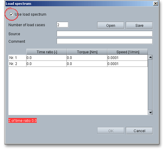
Click the button ‘Load spectrum’. Once the option ‘Use load spectrum’ has been activated, add any number of load spectra with time ratio, torque and speed. The load spectra can be entered manually or imported from files. The load spectra can be saved and loaded. To do this, use the two buttons ‘Open’ and ‘Save’.
The application factor \(K_{A}\) evaluates the external dynamic forces that affect the gearing. These additional forces are largely dependent on the characteristics of the driving and driven machines as well as the masses and stiffness of the system, including shafts and couplings used in service. Because scuffing is not a fatigue failure, the application factor shall consider the stronger influence of several load peaks during the calculation of the scuffing load capacity. Several load peaks affect directly only the flank temperature. Because of that, the same application factor \(K_{A}\) can be used for the calculation of the scuffing load capacity as well as of the load capacity of the tooth root and tooth flank. The application factor is determined by experience. An application factor of ‘1.0’ is best thought of a perfectly smooth operation. The following table gives some values according to DIN 3990.
| Application Factors \(K_{A}\) According to DIN 3990-1: 1987-123
| ||||
| Working Characteristics | Working Characteristics of the Driven Machine | |||
| of the Driving Machine | Uniform | Light shocks | Moderate shocks | Heavy shocks |
| Uniform | 1.0 | 1.25 | 1.5 | 1.75 |
| Light shocks | 1.1 | 1.35 | 1.6 | 1.85 |
| Moderate shocks | 1.25 | 1.5 | 1.75 | 2.0 |
| Heavy shocks | 1.5 | 1.75 | 2.0 | 2.25 or higher |
| 3 from: DIN 3990 Part 1, December 1987, p. 55, table A1
| ||||
Please Note: You will find a ‘Question mark’ button next to the input field. Click on this button and the above-mentioned table opens. The ‘Question mark’ button is an additional feature and provides further information. You will find this button next to several input fields.

The face load factor takes into account the effects of the non-uniform distribution of load over the gear facewidth
on the surface stress \(K_{H\beta }\), on the tooth root stress \(K_{F\beta }\) and on the scuffing \(K_{B\beta }\). The face load factor for the pairing sun
gear-planet gear and planet gear-annulus gear can be defined individually or determined according to DIN
3990, Part 1 Method C. Click on the ‘Calculator’ button to open the input mask for the face load
factor.
When you start the calculation module, the value ‘1.25’ for both pairings sun gear-planet gear and planet gear-annulus gear is entered into the input field. In case you already use a defined face load factor, you can save the certain factor to a template file. Then the calculation module starts with the individual face load factor. When you click on the calculator symbol, the input mask for the face load factor opens.

Select the entry ‘DIN 3990 T1 Method C’. As soon as you select this entry from the listbox, the remaining input fields and listboxes are enabled. The face load factor is determined automatically. Click the button ‘OK’.
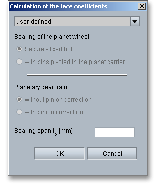
Bearing of the planet gear: Bigger planet gears (for rolling bearings approx. from i > 4) are usually pivoted
about the drive axis. The free bending length is very small. For smaller gear trains (i.e., for smaller ratios) it is
often difficult to accommodate the bearings in the casing. The bearings are attached by means of lateral pins.
The pins are supported on both sides in the planet carrier.
Planetary gear train with or without pinion correction: Errors in manufacturing and elastic deformations that may influence the load capacity can be adjusted by using intentional deviations from the involute (modification of the tooth depth) and theoretical tooth trace (modification of the facewidth). Lead crowning and end relief are the most important pinion corrections and are advantageous for a good load distribution over the facewidth of a gear. Due to lead crowning or end relief, a non-uniform load distribution can be reduced.
Lubrication serves several purposes but its basic and most important function is to protect the sliding and rolling tooth surfaces from seizing, wear and friction. The friction of the tooth flank is responsible for flank wear, gear heating and gear noise. A reduced flank friction improves the efficiency that is dependent on the tooth load, circumferential velocity, gear quality and the surface condition of the tooth flanks. In order that the gearing should work properly, the selection of a lubricant is an important choice. A liquid lubricant is a good choice and can be easily introduced between the contacting surfaces. In addition, a lubrication has to reduce frictional heat and has to protect the surfaces against corrosion. The bearings and clutches in a gearing require also an appropriate lubricant. Therefore, the lubricant has to be suitable as well. Oil and greases are the most common lubricants. The compounding of oils provides a combination and generation of various properties. Oil offers a wider range of operating speeds than greases. They are easier to handle and are most effective. Special E.P. (extreme pressure) oils have been developed for slow-speed, highly-loaded vehicle gears. These oils develop chemical compounds on the contacting gear-tooth surfaces. Grease is a combination of liquid and solids. Grease has the advantage of remaining in place and not spreading as oil. It can provide a lubricant film at heavily loads and at low speeds.

For the selection of liquid lubricants applies: the smaller circumferential velocity and larger the contact pressure
as well as the roughness of tooth flanks, the higher the viscosity. A higher viscosity will result in a higher
hydrodynamic load capacity and an increased scuffing load limit where scratching and scuffing of the tooth
flanks occur (Muhs/Wittel/Jannasch/Vossiek: Roloff/Matek Maschinenelemente, 17th revised edition, published
by Vieweg, Wiesbaden 2005).
Please Note: If the viscosity is too low, the oil film will not be sufficiently formed and if the viscosity is too high,
the viscosity resistance will also be high and cause temperature rise. For higher speed, a lower viscosity oil
should be used and for heavy loads, a higher viscosity oil should be used.
Gears that are running primarily in a gearbox are lubricated with oil. A distinction is made between oil splash
lubrication and oil injection lubrication. The gear mesh and the bearings of planetary gear trains receive
the oil from the shaft. The oil is supplied to the tooth mesh through holes in the tooth root of the
pinion.
Oil splash lubrication: The oil splash lubrication is an easy, reliable and reasonable lubrication system.
It is a type of lubrication used in enclosed gear drives. In splash lubrication, the gear tooth dips
into a tray of lubricant and transfers the lubricant to the meshing gear as it rotates. As a result, oil
reaches all of the places where it is needed. The oil splash lubrication can be used for average speed
applications.
Oil injection lubrication: With the oil injection lubrication, the oil can be filtered, cooled and checked and the oil is
directly fed to the bearings. The amount of oil can be controlled according to the heat dissipation requirements.
The gearbox is used as an oil tank reservoir from which several units can be supplied. The oil is sprayed directly
by a pump injector into the mating surfaces.
Grease lubrication: The selection of the grease is dependent upon the circumferential velocity, the kind of
application and the service temperature. A grease lubrication requires low maintenance and protects against
contamination. Grease lubrication is suitable for any gear system that is opened or enclosed, so long as it runs
at low speed. The grease should have a suitable viscosity with good fluidity especially in a enclosed gear
unit.
Click on the ‘Lubricant’ button and open database. The extensive database contains the lubricants including all detailed information about the oils and greases (e.g., density, viscosity, load stage of FZG test). You can find out more about the FZG test in section 9.9.5 ‘Extended Input Options for Scuffing Load Capacity’.
Select ‘User defined input’ from the listbox to define your individual lubricant.

Click the corresponding button in the main screen of the load capacity to open the advanced input options. If you do not change any entries in the following screen, the calculation continues with the default input values.

If you do not change any entries in the following mask, the calculation continues with the default input values.

The dynamic coefficient \(K_{V}\) considers additional inner dynamic forces. Inner dynamic forces are caused by mesh
alignments, lead crowning, deformation of teeth, the housing, shafts and gear bodies as well as oscillation of the
wheel masses. As the circumferential velocity of the gear rim increases, the dynamic forces increase. The forces
decrease with an increasing load of the teeth. Click the ‘Lock’ button to change the dynamic coefficient for the
gear pairing sun gear-planet gear and planet gear-annulus gear. Click the right or left arrow to select the
pair.
The transverse coefficients account for the effect of the non-uniform distribution of transverse load between
several pairs of simultaneously contacting gear teeth on the surface pressure (\(K_{H\alpha }\)), stress leading to scuffing (\(K_{B\alpha }\)) and
loading of the tooth root (\(K_{F\alpha }\)). Click the ‘Lock’ button to change the transverse coefficient for the gear pairing sun
gear-planet gear and planet gear-annulus gear.
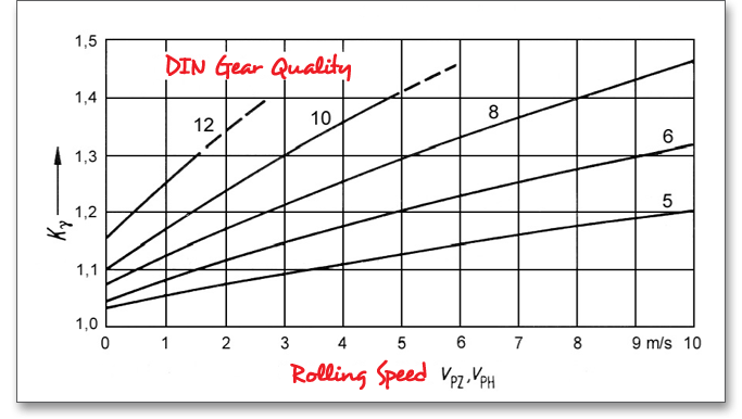
In order to use the advantages of planetary gear trains in an optimal way, it is generally desirable to accomplish an even load distribution. But backlash and unavoidable gear tooth manufacturing accuracy of the gearing can lead to an uneven load distribution on the planet gears. The total circumferential force is unevenly distributed. The mesh load factor \(K_{\gamma }\) takes into account an uneven distribution of the total circumferential force for gearings with transmission paths or for planetary gear trains with more than three planets. For transmission paths, the total circumferential force is distributed to several meshes. A high manufacturing quality can improve the load distribution. In 2008, Germanische Lloyd required the following mesh load factors:
| Mesh Load Factor
| ||||
| Number of planets | Up to three planets | 4 planets | 5 planets | 6 planets |
| \(K_{\gamma }\) | 1.0 | 1.2 | 1.3 | 1.6 |
Niemann (Niemann, G.: Maschinenelemente Band II, Springer Verlag Berlin, 1989, p. 361, figure 22.5/2d) recommends the following values (depending on the gear quality and the sliding velocity).
When the facewidth of pinion and gear is not equal, then a maximum overhang of ‘1 x m’ at each
tooth end is assumed as a carried width. Unhardened portions of surface-hardened gear tooth
flanks (including transition zone) consider only 50% as the carried width. However, if it is foreseen
that because of crowning or end relief the contact does not extend to the end of face, then the
smaller facewidth shall be used for both pinion and gear. Click the ‘Lock’ button to change the carried
width.
In specific cases, the development of pits on the gear flank is allowed. Use this option to permit several pits. In general, initial pitting is considered normal and is not a cause for concern. In particular, case-hardened and nitrided gears usually has the tendency to pit near the tooth root and lead eventually to fatigue breakage. Here an individual assessment is necessary. In some cases (aerospace industry), pits are absolutely not permitted. For turbo transmissions, pits may lead to oscillations and increased additional dynamic forces.
The main mask of the load capacity provides the ‘Tooth root/flank’ button, click on that button and the extended input options appear. If you do not change any inputs in the following mask, then the default input values are used. You can use the arrow to quickly toggle between the gear pairing sun gear-planet gear or planet gear-annulus gear.
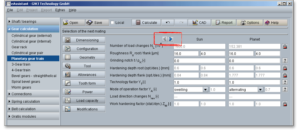
The surface roughness of the tooth flanks influences the load capacity of the tooth flanks. The average
roughness \(R_{z}\) is the arithemitc average of five individually measured roughness values. The input of the roughness
occurs for root and flank of pinion and gear. The right choice of the surface roughness is determined by
economical aspects depending upon the intended purpose and manufacturing process. A fine surface can be
very expensive because of the high manufacturing costs. A surface that is too rough may not fulfill the required
functionality.
A grinding notch may significantly reduce the fatigue strength and a tooth breakage can occur due to a grinding notch.
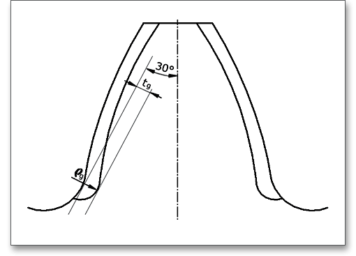
Shot-peening can be used to increase the fatigue strength of gears that are damaged by a grinding notch.
A careful grinding of the notch is basically suitable. Click the ‘Question mark’ button to open the
figure.
The hardening depth is significantly for the pitting load capacity and is determined by the depth of surface layer heated to hardening temperature, the hardenability of the material and the effect of the quenching method. Case-hardening: Steels get their specific features by case-hardening. This combined heat treatment process consists of the following subprocesses:
Please Note: The calculation module determines the optimal hardening depth automatically, but the hardening
depth can be defined also individually. If the individual hardening depth is smaller than the optimal hardening
depth, then the fatigue strength is reduced accordingly. The determination of the optimal hardening depth and
reduction of fatigue strength with reduced hardening depth is based on: „Tobie, Thomas: Zur Gruebchen-
und Zahnfussragfaehigkeit einsatzgehaerteter Zahnraeder, Dissertation Technische Universitaet
Muenchen (Lehrstuhl fuer Maschinenelemente, Forschungsstelle fuer Zahnraeder und Getriebebau)
2001, Section. 10.3: Eingliederung der Versuchsergebnisse in das Rechenverfahren nach DIN
3990“.
The technology factor \(Y_{T}\) considers the change of the strength of the tooth root by machining process.
\[\sigma _{Flim} = \sigma _{Flim0} Y_{T}\]
| \(\sigma _{Flim0}\) | Fatigue strength of the tooth root from material data |
| \(\sigma _{Flim}\) | Fatigue strength of the tooth root with influence of the technology factor |
| \(Y_{T}\) | Technology factor (see following table) |
| Technology Factor \(Y_{T}\) According to Linke4
| |
| Kind of Manufacturing of the Tooth Root | Technology Factor \(Y_{T}\) |
| Shot peening: | 1.2 to 1.4 |
| Applies for case-hardened or carbonitrided gears; not ground in the hardened layer |
|
| Rolling: | 1.3 to 1.5 |
| Applies for flame and induction hardened gears; not ground in the hardened layer |
|
| Grinding: | General: 0.7 |
| Applies for case-hardened or carbonitrided gears | for CBN grinding wheel: 1 |
| Shape cutting: | 1 |
| Does not apply for ground gears |
|
| 4 from: Linke, H.: Stirnradverzahnung Berechnung Werkstoffe Fertigung, Carl Hanser Verlag
Muenchen Wien, 1996, p. 320, table 6.5/6
| |
Click the ‘Question mark’ button to open the tables for the technology factor and mode of operation factor.

The fatigue strength of the tooth root \(\sigma _{Flim}\) is corrected with the influence of the mode of operation.
\[\sigma _{Flim} = \sigma _{Flim0} Y_{A}\]
| \(\sigma _{Flim0}\) | Fatigue strength of the tooth root from material data |
| \(\sigma _{Flim}\) | Fatigue strength of the tooth root with influence of the mode of operation factor |
| \(Y_{A}\) | Mode of operation factor (see following table) |
The following reference values can be used for the mode of operation factor \(Y_{A}\). DIN 3990 specifies identical values for swelling and alternating load.
| Mode of operation factor \(Y_{A}\) according to Linke5
| ||
| Mode of Operation | Mode of Operation Factor \(Y_{A}\) | Direction of Load |
| Swelling | 1 |  |
| Alternating | 0.7 |  |
| Oscillating | 0.85 - 0.15 \(\frac {lgN_{rev}}{6}\) (for \(1\leq N_{rev} \leq 10^{6}\)) 0.7 (for \(N_{rev} > 10^{6}\)) | 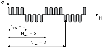 |
| Please Note: \(N_{rev}\) = Number of load direction changes during operation time
| ||
| 5 from: Linke, H.: Stirnradverzahnung Berechnung Werkstoffe Fertigung, Carl Hanser Verlag
Muenchen Wien, 1996, p. 321, table 6.5/7
| ||
The scuffing load capacity offers different extended input options. Click on the ‘Scuffing’ button and the extended input options appear.
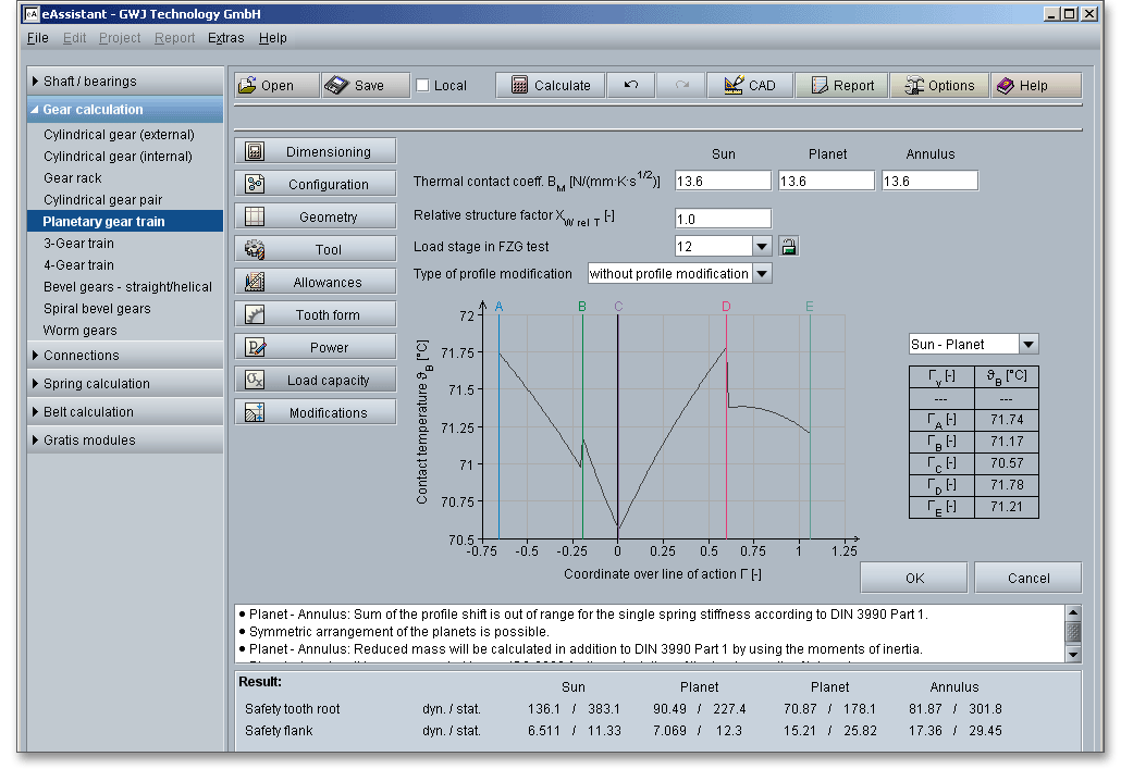
The thermal contact coefficient \(B_{M}\) is required for the determination of the flash factor. The flash factor considers the influence of the material properties of gear and pinion on the flash temperature.

The relative structure factor \(X_{WrelT}\) is primarily intended to take into account influence of the material properties on the scuffing load capacity and is determined by:
\[X_{WrelT} = \frac {X_{W}}{X_{WT}}\]
| \(X_{W}\) | The lower table provides the empirically determined relative structure factor. |
| \(X_{WT}\) | The relative structure factor for the test gears that are used for the determination of the scuffing |
| temperature. \(X_{WT}\) = 1.0 for the FZG gear test. |
| Material/Heat Treatment | Structure Factor \(X_{W}\) |
| Through-hardened steel | 1.00 |
| Phosphated steel | 1.25 |
| Copper plated steel | 1.50 |
| Bath and gas nitrided steel | 1.50 |
| Hardened carburized steel, with austenite content: | |
| - less than average | 1.15 |
| - average | 1.00 |
| - greater than average | 0.85 |
| Austenitic steel (stainless steel) | 0.45 |
| 6 from: Linke, H.: Stirnradverzahnung Berechnung Werkstoffe Fertigung, Carl
Hanser Verlag Muenchen Wien, 1996, p. 367, table 6.5/16
| |
Because scuffing is not a fatigue failure, a standard FZG gear test was developed to determine the scuffing load capacity of a lubricant under certain operating conditions. The gear test, known as FZG gear test (Institute for Machine Elements Gear Research Center, University Munich, Germany), is a standardized method according to DIN 51354. At the FZG, the different influences on scuffing are extensively investigated. The test is performed on a standard FZG test machine using standard test gears. Standardized, case-hardened and ground spur gears with a large one-side profile shift are used. The load is increased gradually on a FZG gear test rig with defined technical parameters. There are 12 load stages and the gears are inspected for scuffing after every load stage. Finally, the load stage is determined where scuffing of the gear teeth occurs and where the flank area is damaged by scratches. The higher the load stages, the better the industrial gear lubricants resistance to scuffing. Not all lubricants have a defined load stage. If you click the ‘Lock’ button next to the listbox of the load stage, the input field is enabled and you can choose a load stage.

For high-duty gearings, it is possible to change the theoretical involute. Using the listbox to define the type of profile modification. You can select the following options: without profile modification, for high-duty gearing and for uniform mesh.

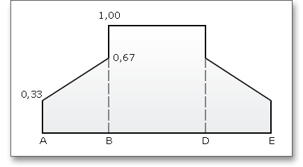
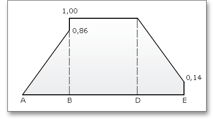
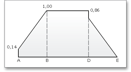
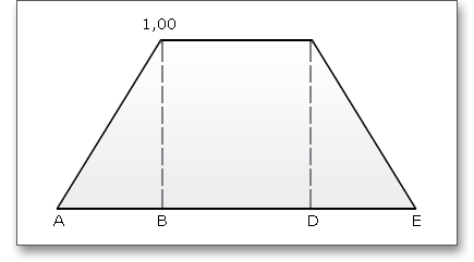
The force distribution factor \(X_{\Gamma }\) evaluates the influence of the force distribution over several pairs of meshing teeth. A polygon-like shape over the line of action represents the progress of the force distribution factor. The values of the points A and E depend upon the type of profile modification. According to DIN 3990 (see Part 4, p. 17), the force distribution factor is as follows:
The contact temperature varies along the path of contact due to the progress of the flash temperature.


High surface temperatures due to high loads and slidings speeds can cause a lubricant film breakdown. Because of that, there are two calculation methods in ISO/TR 13989 that are based on different criteria for the development of a damage. The eAssistant software provides both the integral temperature method and flash temperature method:
The flash temperature is the temperature at which a gear-tooth surface is calculated to be hot enough to destroy the oil film and allow instantaneous welding at the contact point. The contact temperature \(\vartheta _{B}\) in any point of contact \(Y\) results from the sum of the bulk temperature \(\vartheta _{M}\) and the flash temperature \(\vartheta _{fla}\):
\[\vartheta _{B} = \vartheta _{M} + \vartheta _{fla}\]
According to the flash temperature method, there is no scuffing as long as the contact temperature \(\vartheta _{B}\) (as the sum of bulk temperature \(\vartheta _{M}\) and flash temperature \(\vartheta _{fla}\)) does not exceed the scuffing contact temperature in all points of contact. The scuffing temperature \(\vartheta _{S}\) to be a characteristic value for the material-lubricant-material system of a gear pair, to be determined by gear tests with the same material-lubricant-material system.
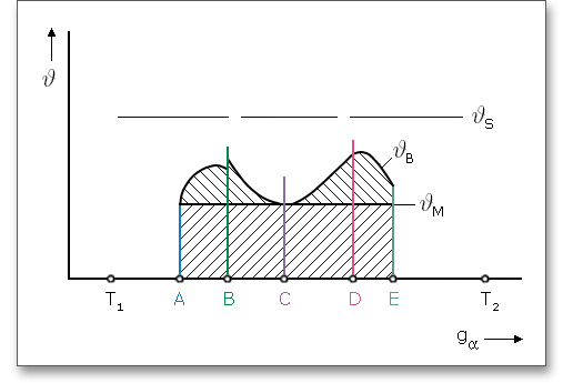
Please note: Points A to E mark the important points from the beginning to the end of the mesh.
The safety against scuffing \(S_{B}\) is determined according to the flash temperature method:
\[S_{B} = \frac {\vartheta _{S} - \vartheta _{oil}}{\vartheta _{Bmax} - \vartheta _{oil}} \geq S_{Bmin}\]
| \(\vartheta _{Bmax}\) | Maximum contact temperature along the path of contact |
| \(\vartheta _{oil}\) | Oil temperature before reaching the mesh |
| \(\vartheta _{S}\) | Scuffing temperature |
The safety factor \(S_{Bmin}\) is dependent on whether the gearing is put into operation after a good running-in period. With
a careful running-in period, there is no scuffing damage up to \(S_{Bmin} \approx 1\). Without a running-in period, there is no scuffing
up to \(S_{Bmin} \approx 3\) (according to Linke).
According to the integral temperature method, scuffing occurs when the integral temperature exceeds the scuffing integral temperature. The scuffing integral temperature is assumed as a characteristic value for the material-lubricant-material system of a gear pair and is determined from gear tests. The scuffing safety according the integral temperature method \(S_{intS}\) is calculated as follows:
\[S_{intS} = \frac {\vartheta _{intS}}{\vartheta _{int}} \geq S_{Smin}\]
| \(\vartheta _{intS}\) | Scuffing integral temperature |
| \(\vartheta _{int}\) | Integral temperature |
As uncertainties and inaccuracies in the assumptions cannot be excluded, it is necessary to introduce a safety factor. According to Linke, the following reference values can be used:
| \(S_{intS} < 1.0\) | In all probability, scuffing damages are expected to occur. |
| \(1.0 \leq S_{intS} \leq 2.0\) | For a careful running-in period of the gearing, good contact pattern and real assumed |
| loads, there are no scuffing damages to be expected. |
| \(S_{intS} > 2.0\) | There is no risk of scuffing. |
In addition to DIN 3990 Method B, it is possible to calculate the load capacity of tooth root and tooth flank according to ISO 6336 (2006, 2019) Method B. Select the ISO 6336 Method B from the listbox and the input fields are enabled.
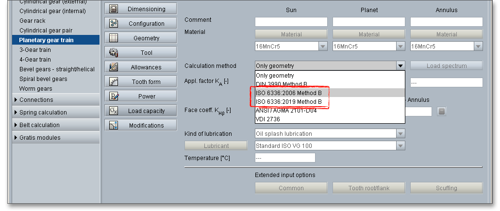
There is a strong similarity between the DIN 3990 standard and the ISO 6336 standard and most parts of the
load capacity calculation according to ISO 6336 correspond to DIN 3990. In fact, the ISO 6336 evolved from the
DIN 3990 standard. There are factors that influence the tooth root stress and tooth flank strength, but
the differences are minor and the influence on the safety of root, flank and scuffing is very low.
Another difference between DIN 3990 and ISO 6336 is the critical stress point on the root fillet. ISO
6336 uses the tangency point of a \(60^{\circ }\) angle as the most critically stressed point on the root fillet for
internal gears. The DIN 3990 standard uses the tangency point of a \(30^{\circ }\) angle as the critical stress
point on the root fillet for external and internal gears as the basis for the calculation of the load
capacity.
The tooth form factor \(Y_{F}\) is the form factor, which represents the influence on nominal tooth root stress of the tooth form with load applied at the outer point of single pair tooth contact. According to DIN 3990, the form factor for external and internal gears is calculated at the tooth root at the point of the \(30^{\circ }\) tangent. This method appeared to be inaccurate, especially for internal gears. ISO 6336 uses the tangency point of a \(60^{\circ }\) angle as the most critically stressed point on the root fillet for internal gears. This method is more precise and leads to higher safeties for the tooth root.
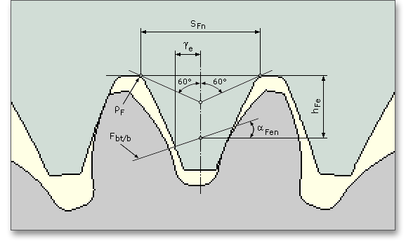
There are significant differences in the calculation of the life factors \(Y_{NT}\) and \(Z_{NT}\) when comparing DIN 3990 and ISO 6336. The long life factor \(Y_{NT}\) accounts the higher tooth root stress and the long life factor \(Z_{NT}\) accounts the higher contact stress including static stress, which may be tolerable for a limited life (number of load cycles). The factors mainly depend on the quality of the material, heat treatment, number of load cycles as well as notch sensitivity, surface conditions and gear dimensions. The life factors \(Y_{NT}\) and \(Z_{NT}\) can be read from the following graph for the static and reference stress as a function of material and heat treatment.
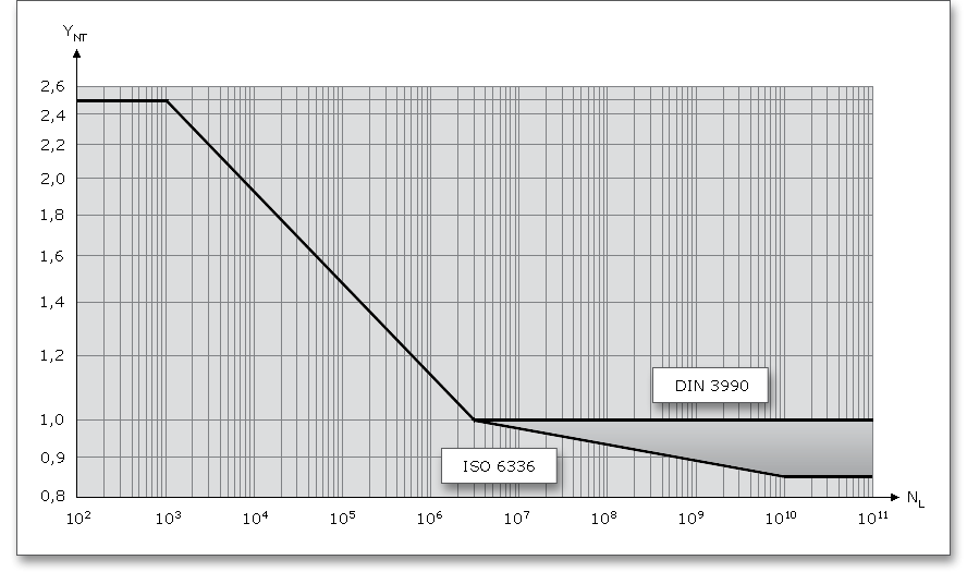
Long life factor \(Y_{NT}\):
With optimum lubrication, material and manufacturing \(Y_{NT}\) = 1.0 may be used for the number of load cycles \(N_{L} = 3 \cdot 10^{6}\). For
static stresses \(N_{L} \leq 10^{3}\), the long life factor is 2.5.
Long life factor \(Z_{NT}\):
With optimum lubrication, material and manufacturing \(Z_{NT}\) = 1.0 may be used for the number of load cycles \(N_{L} = 5 \cdot 10^7\). For
static stresses \(N_{L} \leq 10^{5}\), the long life factor is 1.6.
There are significant differences in the calculation of the life factors \(Y_{NT}\) and \(Z_{NT}\) when comparing DIN 3990 and ISO 6336. Values appropriate to the relevant number of load cycles, \(N_{L}\), are indicated by the S-N curve (also known as a Woehler curve). The S-N approach is different. The long life factor for the load capacity of the tooth root approaches 1.0 for the range of long life (depending on the material, usually at \(3 \cdot 10^6\) load cycles). In DIN 3990, the life factor remains 1.0 for higher number of load cycles. According to ISO 6336, the factor for materials decreases from 1.0 to 0.85 at \(10^{10}\) load cycles. Only after that, the factor remains 0.85 at \(10^{10}\) load cycles. For gears in the long life range, the calculations according to ISO 6336 result in significantly smaller safeties (15% lower) for tooth root and tooth flank. This also applies for the long life factor for flanks. Use the ‘Lock’ button to modify the long life factors \(Y_{NT}\) and \(Z_{NT}\). The input fields are enabled and you can define your own value for the factors. Please remember to keep the modified input field open or the default values will be used again.

Another difference between ISO and DIN is the determination of the mesh stiffness \(c_{\gamma }\). The mesh stiffness is
needed for the calculation of the face load factor \(K_{H\beta }\). The factor \(K_{H\beta }\) takes into account uneven distribution of load over
the facewidth due to mesh misalignment caused by inaccuracies in manufacture and elastic deformations. For
the calculation of the face load factor, ISO 6336 uses a mesh stiffness \(c_{\gamma }\) that is reduced by 15% in comparison to
the mean stiffness the DIN 3990 use for the calculation of \(K_{H\beta }\). This results in slightly lower face load
factors.
If the rim thickness is too thin and not sufficient to provide full support for the tooth root (e.g., for planetary gear
trains or internal gears), then this can be accounted for by the rim thickness factor \(Y_{B}\). \(Y_{B}\) is expressed as a function
of the tooth depth for external gears and as a function of the normal module for internal gears. The load capacity
decreases with a gear rim thickness \(s_{R} < 1.2 \cdot h_{t}\) for external gears or \(2.8 \cdot m_{n}\), for internal gears \(s_{R} < 3.5 \cdot m_{n}\) (ISO 6336 Edition 2006 - Was ist
neu?: Dr.-Ing. R. Hess, Dipl.-Ing. B. Kisters, A. Friedr. Flender AG, Bocholt, Tagungsbeitrag Dresdener
Maschinenelemente Kolloquium 2009).
Another difference is the determination of the helix angle factor \(Z_{\beta }\). Independent of the influence of the helix angle on the length of path of contact, this factor accounts for the influence of the helix angle on the load capacity of the tooth flanks, allowing for such variables as the distribution of load along the lines of contact. \(Z_{\beta }\) is dependent only on the helix angle, \(\beta \). The given formulae for the determination of the helix angle factor are different in DIN 3990 and ISO 6336. DIN 3990 gives the following formular to calculate the helix angle factor (\(\beta \) is the helix angle at reference circle):
\[Z_{\beta } = \sqrt {\cos \beta }\]
In ISO 6336, the helix angle factor is defined as follows:
\[Z_{\beta } = \frac {1}{\sqrt {\cos \beta }}\]
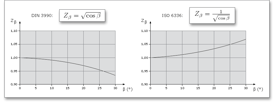
The work hardening factor \(Z_{W}\) has been revised in ISO 6336. This factor is used to take into consideration the
Hertzian pressure which serves as a basis for the calculation of the load capacity of the tooth flanks. The work
hardening factor accounts for the increase in surface durability due to meshing a steel gear with a hardened
or substantially harder pinion with smooth tooth flanks. In DIN 3990 and the previous version of
ISO 6336, the work hardening factor was dependent solely on the flank hardness of the softer
gear.
The increase in the surface durability of the soft gear depends not only on any work hardening of this gear, but
also on other influences such as flank surface roughness. In addition, the influence of the surface roughness is
addressed in ISO 6336. Tooth flank curvature, pitch line velocity and lubricant viscosity are taken into account in
the calculation. The work hardening factor is reduced for gears with hard, rough surface. Gear teeth with rough
surfaces may wear a softer mating teeth. Wear of the surface is not covered by ISO 6336. Especially for rough
pinion surfaces, values of \(Z_{W}\) < 1 may be evaluated. As in this range effects of wear can limit the surface
durability, \(Z_{W}\) is fixed at \(Z_{W}\) = 1.0 (ISO 6336 Edition 2006 - Was ist neu?: Dr.-Ing. R. Hess, Dipl.-Ing. B.
Kisters, A. Friedr. Flender AG, Bocholt, Tagungsbeitrag Dresdener Maschinenelemente Kolloquium
2009).
ISO 6336 does not provide a calculation method for scuffing. For the safety against scuffing, the Technical Report ISO/TR 13989 shall be preferably used. ISO/TR 13989 is a Technical Report (March 2000). This document is not to be regarded as an ‘International Standard’. It is proposed for provisional application so that information and experience of its use in practice may be gathered.
The scuffing load capacity is calculated according to ISO/TR 13989 Part 1 (Flash temperature method) and Part 2 (Integral temperature method) as soon as you select ‘ISO 6336 Method B’.
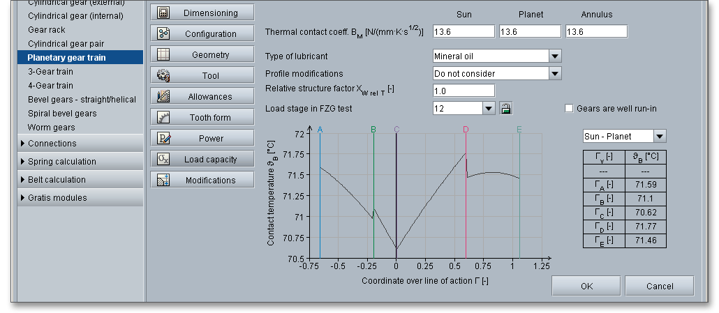
The thermal contact coefficient \(B_{M}\) is required for the determination of the flash factor. The flash factor considers
the influence of the material properties of gear and pinion on the flash temperature.
The lubricant factor \(X_{L}\) depends on the the type of lubricant. You can select the following types:

The relative structure factor \(X_{WrelT}\) is primarily intended to take into account influence of the material properties on the scuffing load capacity and is determined by:
\[X_{WrelT} = \frac {X_{W}}{X_{WT}}\]
| \(X_{W}\) | The lower table provides the empirically determined relative structure factor. |
| \(X_{WT}\) | The relative structure factor for the test gears that are used for the determination of the scuffing |
| temperature. \(X_{WT}\) = 1,0 for the FZG gear test. |
| Material/Heat Treatment | Structure Factor \(X_{W}\) |
| Through-hardened steel | 1.00 |
| Phosphated steel | 1.25 |
| Copper plated steel | 1.50 |
| Bath and gas nitrided steel | 1.50 |
| Hardened carburized steel, with austenite content: | |
| - less than average | 1.15 |
| - average | 1.00 |
| - greater than average | 0.85 |
| Austenitic steel (stainless steel) | 0.45 |
| 7 from: Linke, H.: Stirnradverzahnung Berechnung Werkstoffe Fertigung, Carl
Hanser Verlag Muenchen Wien, 1996, p. 367, table 6.5/16
| |
Because scuffing is not a fatigue failure, a standard FZG gear test was developed to determine the scuffing load capacity of a lubricant under certain operating conditions. The gear test, known as FZG gear test (Institute for Machine Elements Gear Research Center, University Munich, Germany), is a standardized method according to DIN 51354. At the FZG, the different influences on scuffing are extensively investigated. The test is performed on a standard FZG test machine using standard test gears. Standardized, case-hardened and ground spur gears with a large one-side profile shift are used. The load is increased gradually on a FZG gear test rig with defined technical parameters. There are 12 load stages and the gears are inspected for scuffing after every load stage. Finally, the load stage is determined where scuffing of the gear teeth occurs and where the flank area is damaged by scratches. The higher the load stages, the better the industrial gear lubricants resistance to scuffing. Not all lubricants have a defined load stage. If you click the ‘Lock’ button next to the listbox of the load stage, the input field is enabled and you can choose a load stage.

High surface temperatures due to high loads and sliding speeds can cause a lubricant film breakdown. Because of that, there are two calculation methods in DIN 3990 that are based on different criteria for the development of a damage. The eAssistant software provides both the integral temperature method and flash temperature method:
The flash temperature is the temperature at which a gear-tooth surface is calculated to be hot enough to destroy the oil film and allow instantaneous welding at the contact point. The contact temperature \(\vartheta _{B}\) in any point of contact \(Y\) results from the sum of the bulk temperature \(\vartheta _{M}\) and the flash temperature \(\vartheta _{fla}\):
\[\vartheta _{B} = \vartheta _{M} + \vartheta _{fla}\]
According to the flash temperature method, there is no scuffing as long as the contact temperature \(\vartheta _{B}\) (as the sum of bulk temperature \(\vartheta _{M}\) and flash temperature \(\vartheta _{fla}\)) does not exceed the scuffing contact temperature in all points of contact. The scuffing temperature \(\vartheta _{S}\) to be a characteristic value for the material-lubricant-material system of a gear pair, to be determined by gear tests with the same material-lubricant-material system.
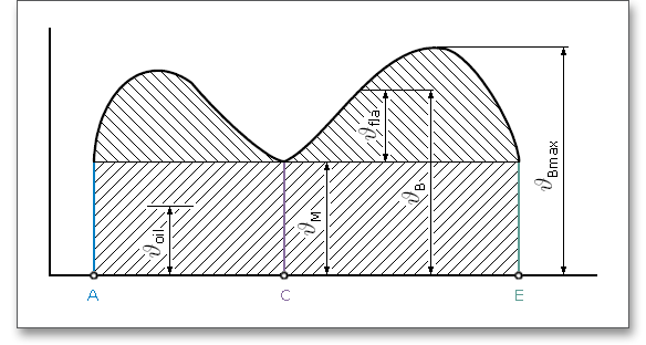
The safety against scuffing \(S_{B}\) is determined according to the flash temperature method:
\[S_{B} = \frac {\vartheta _{S} - \vartheta _{oil}}{\vartheta _{Bmax} - \vartheta _{oil}}\]
| \(\vartheta _{Bmax}\) | Maximum contact temperature along the path of contact |
| \(\vartheta _{oil}\) | Oil temperature before reaching the mesh |
| \(\vartheta _{S}\) | Scuffing temperature |
The safety factor \(S_{Bmin}\) is dependent on whether the gearing is put into operation after a good running-in period. With
a careful running-in period, there is no scuffing damage up to \(S_{Bmin} \approx 1\). Without a running-in period, there is no scuffing
up to \(S_{Bmin} \approx 3\) (according to Linke).
According to the integral temperature method, scuffing occurs when the integral temperature exceeds the scuffing integral temperature. The scuffing integral temperature is assumed as a characteristic value for the material-lubricant-material system of a gear pair and is determined from gear tests. The scuffing safety according the integral temperature method \(S_{intS}\) is calculated as follows:
\[S_{intS} = \frac {\vartheta _{intS}}{\vartheta _{int}} \geq S_{Smin}\]
| \(\vartheta _{intS}\) | Scuffing integral temperature |
| \(\vartheta _{int}\) | Integral temperature |
As uncertainties and inaccuracies in the assumptions cannot be excluded, it is necessary to introduce a safety factor. According to Linke, the following reference values can be used:
| \(S_{intS} < 1.0\) | In all probability, scuffing damages are expected to occur. |
| \(1.0 \leq S_{intS} \leq 2.0\) | For a careful running-in period of the gearing, good contact pattern and real assumed |
| loads, there are no scuffing damages to be expected. |
| \(S_{intS} > 2.0\) | There is no risk of scuffing. |
The standard provides the calculation of safeties for the root and flank. Further the calculation of risk of scuffing is also available. Additional to the DIN 3990 and ISO 6336 standard, the ANSI/AGMA 2101-D04 provides also the calculation of wear. The eAssistant software calculates the wear as failure probability. Select ANSI/AGMA 2101-D04 from the listbox and the input fields are enabled. The following explains some factors from the standard.
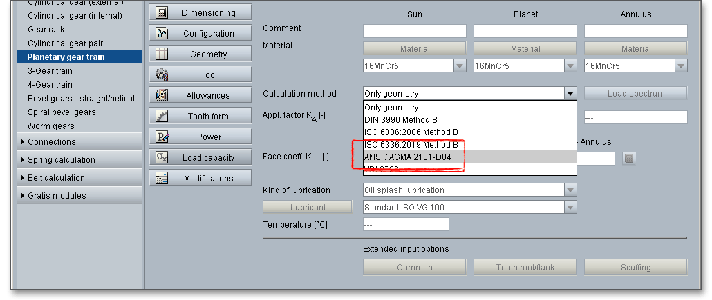
With the new edition of the ANSI/AGMA 2101-D04 (ANSI/AGMA 2001-D04 imperial unit edition, the application
factor from ANSI/AGMA 2101-C95 was replaced by overload factor \(K_{O}\).
The overload factor is intended to make allowance for all externally applied loads in excess of the nominal
tangential load, \(F_{t}\), for a particular application. Overload factors can only be established after considerable field
experience is gained in a particular application.
For an overload factor of unity, this rating method includes the capacity to sustain a limited number of up
to 200 % momentary overload cycles (typically less than four starts in 8 hours, with a peak not
exceeding one second duration). Higher or more frequent momentary overloads shall be considered
separately.
In determining the overload factor \(K_{O}\), consideration should be given to the fact that many prime movers and driven equipment, individually or in combination, develop momentary peak torques appreciably greater than those determined by the nominal ratings of either the prime mover or the driven equipment. There are many possible sources of overload which should be considered. Some of these are: system vibrations, acceleration torques, overspeeds, variations in system operation, split path load sharing among multiple primemovers, and changes in process load conditions.
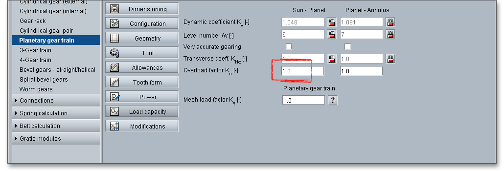
The stress cycle factors, \(Z_{N}\) and \(Y_{N}\), adjust the allowable stress numbers for the required number of cycles of
operation. For the purpose of this standard, \(n_{L}\), the number of stress cycles is defined as the number of mesh
contacts, under load, of the gear tooth being analyzed.
AGMA allowable stress numbers are established for \(10^{7}\) unidirectional tooth load cycles at 99 % reliability. The
stress cycle factor adjusts the allowable stress numbers for design lives other than \(10^{7}\) cycles. The stress cycle
factor accounts for the S-N characteristics of the gear material as well as for the gradual increased tooth stress
which may occur from tooth wear, resulting in increased dynamic effects and from shifting load distributions
which may occur during the design life of the gearing.
Standard surface condition factor \(Z_{R}\) for gear teeth have not yet been established for cases where there is a
detrimental surface finish effect. In such cases, some surface finish factor greater than unity should be used.
The surface condition factor can be taken as unity provided the appropriate surface condition is
achieved.
The size factor \(K_{S}\) reflects non-uniformity of material properties. It depends primarily on: tooth size, diameter of parts, ratio of tooth size to diameter of part, facewidth, area of stress pattern, ratio of case depth to tooth size, hardenability and heat treatment of materials. Standard size factors for gear teeth have not yet been established for cases where there is a detrimental size effect. In such cases, some size factor greater than unity should be used. The size factor may be taken as unity for most gears, provided a proper choice of steel is made for the size of the part and its heat treatment and hardening process.
The temperature factor \(Y_{\vartheta }\) is generally taken as unity when gears operate with temperatures of oil or gear blank not exceeding 120°C. When operating temperatures result in gear blank temperatures below 0°C, special care must be given. When operating at oil or gear blank temperature above 120°C, \(Y_{\vartheta }\) is given a value greater than 1.0 to allow for the effect of temperature on oil film and material properties. Consideration must be given to the loss of hardness and strength of some materials due to the tempering effect of temperatures over 150°C.
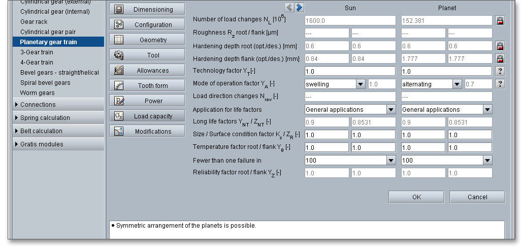
The reliability factors \(Y_{Z}\) account for the effect of the normal statistical distribution of failures found in materials testing. The allowable stress numbers given in ANSI/AGMA (tables 3 through 6) are based upon a statistical probability of one failure in 100 at \(10^{7}\) cycles. The following table contains reliability factors which may be used to modify these allowable stresses to change that probability. These numbers are based upon data developed for bending and pitting failure by the U.S. Navy. Other values may be used if specific data is available.
| Reliability Factor \(Y_{Z}\)110
| |
| Requirements of Application | \(Y_{Z}\) |
| Fewer than one failure in 10 000 | 1.50 |
| Fewer than one failure in 1000 | 1.25 |
| Fewer than one failure in 100 | 1.00 |
| Fewer than one failure in 10 | 0.852 |
| Fewer than one failure in 2 | 0.7023 |
| Notes: 1) Tooth breakage is sometimes considered a greater hazard than
pitting. In such cases a greater value of \(Y_{Z}\) is selected for bending. 2) At this value
plastic flow might occur rather than pitting. 3) From test data extrapolation.
| |
| 10 from: ANSI/AGMA 2001-D04: Fundamental Rating Factors and Calculation
Methods for Involute Spur and Helical Gear Teeth, 2016, p. 38, table 11
| |
The service factor \(C_{SF}\) has been used in previous AGMA standards to include the combined effects of overload,
reliability, life and other application related factors. This standard provides a means to account for: variations in
load (with overload factor), statistical variations in S-N data (with reliability factor), and the number of design
stress cycles (with stress cycle factor).
The AGMA service factor as traditionally used in gear applications depends on experience acquired in each
specific application. Product application standards can be a good source for the appropriate value of service
factor. Equations 28 and 29 of AGMA 2101-D04 are used to establish power ratings for unity service factor to
which established service factors may be applied using equation 30. When this is done, the stress cycle factor is
calculated using the number of cycles equivalent to a specific number of hours at a specific speed, to establish
power rating for unity service factors.
Where specific experience and satisfactory performance has been demonstrated by successful use of
established service factors, values of \(Z_{N}\) and \(Y_{N}\) of 1.0 may be appropriate.
For gears made of plastic, the load capacity can be calculated according to VDI 2736. Select VDI 2736 from the listbox. All input fields are activated. The load capacity calculation of cylindrical gears made of thermoplastics is based on DIN 3990, which applies to metallic materials. The same damage can occur on plastic gears as on steel gears: pitting, wear or tooth breakage.
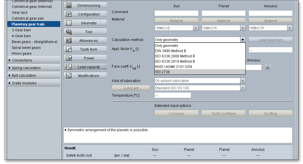
Compared to metals, thermoplastics have some special features, e.g.
Positive properties compared to steel gears:
Plastic gears are used in particular where quiet running is important because plastics have a vibration-damping
effect. They are mainly used for precision engineering equipment, textile machines and domestic
appliances.
It is recommended to calculate the load capacity for plastic gears according to VDI 2736. However, in
eAssistant it is also possible to calculate the load capacity using DIN 3990, ISO 6336 and ANSI/AGMA
2101-D04. The recalculation of the tooth root load capacity according to VDI 2736 is based on the tooth root
stress with force application on the tooth tip and on the assumption of pure bending stress. In DIN 3990 Method
B, the force is applied to the outer single contact point and the calculation is much more accurate. In
VDI 2736, DIN 3990 is referred to in some places as an alternative. If reference is made to DIN
3990, then the calculation of the load capacity in the eAssistant is carried out according to this
standard.
The plastics can be selected from the general material database. For this, the temperature-dependent material properties such as fatigue strength and E-module were approximated in detail from available diagrams in VDI 2736 and stored accordingly. These are used to determine the material properties for the calculation of the load capacity using the tooth root and flank temperatures automatically calculated according to VDI 2736. If the calculated tooth flank and tooth root temperatures exceed the maximum operating temperatures of the plastics, you will get a corresponding warning in the message window. When calculating the load capacity according to DIN 3990, ISO 6336 and ANSI/AGMA 2101-D04, the material parameters are selected on the basis of the lubricant temperature.
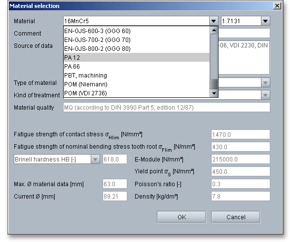
Please Note: PA and POM gears have a higher load capacity and better heat dissipation when paired with a
metal wheel. If possible, never pair the same plastics. The noise behavior with pairing thermoplastic gears is
more favorable than with plastic/metal.
In order to calculate the tooth flank and tooth root temperature, you can modify the housing design, the
heat-dissipating surface as well as the heat transfer and heat resistance as an alternative to the automatic
default settings.
Both plastic/plastic and plastic/metal pairings are possible as material pairings. Furthermore, metal/metal pairings are also available in order to compare calculation methods for metallic gears. The calculation of load spectra is also possible for the load capacity calculation according to VDI 2736. Plastic gears are often operated under dry running conditions. Select the option ‘Dry running’ from the listbox ‘Kind of lubrication’.

Manufacturing errors, misalignment in the assembly of the gears as well as displacement of the gears under load lead to non-uniform load carrying across the facewidth and move a significant concentration of load to the tooth edges. Intentional deviations from the involute profile (profile modification) and from the theoretical tooth trace (flank modification) are used to minimize the manufacturing inaccuracies and elastic deformations, to improve the running behavior and to reduce the noise of the gear pair.
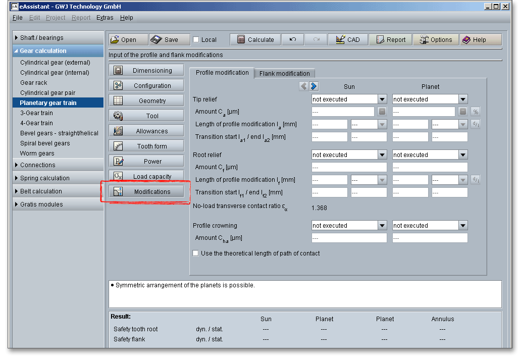
There are different types of tooth corrections. Short and long linear or short and long circular tip and
root relief are typical tooth profile modifications. Lead crowning and end relief are common flank
modifications. These corrections tend to give better load distribution over the facewidth and can reduce the
effects of misalignment. Using profile or flank modification requires an appropriate degree of gear
accuracy. The minimum required gear manufacturing accuracy is DIN quality 7 or better. Design details
should be based on a careful estimate of the deformations and manufacturing deviations of the
gearing.
In case of gear tooth profile modification, parts of the involute profile are changed to reduce the load in that area. Profile modifications help gears to run more quietly and to regulate transmission errors.
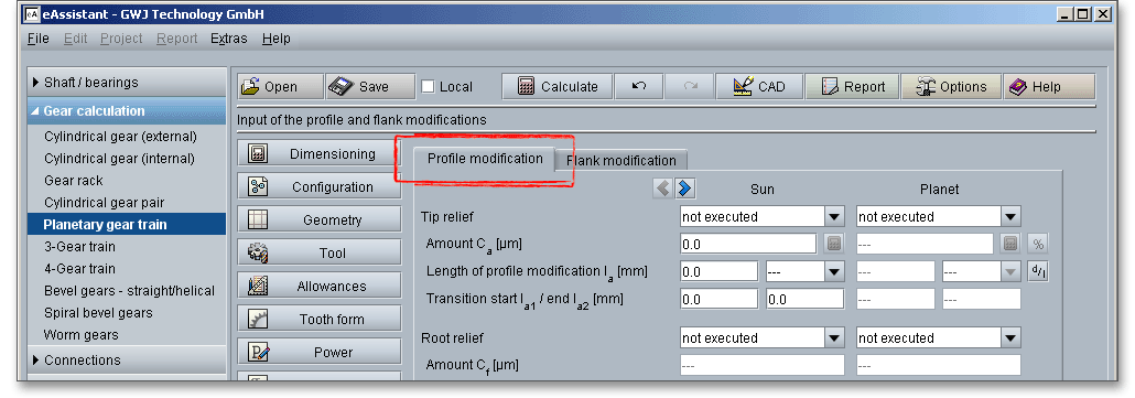
Tip relief is a modification whereby material is removed at the tips of the gear tooth. In case of root relief, a small amount of material is removed near the root of the gear tooth. The modified tooth profile merges as continuously as possible into the theoretical tooth profile. Profile crowning can be seen as a combination of tip and root relief.
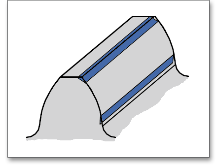
There are different types that can be chosen for the profile modification. A simple type of profile modification is the linear tip relief on pinion and gear. However, it is also possible to execute only one gear with a tip and root relief instead of both gears. The listbox allows to select linear and circular profile modification. The linear relief results in the greatest material removal and thus the greatest relief in the effective flank area.
When determining the lengths of the profile correction, a distinction is made between short and long profile modification. In case of long tip and root relief, the entire double contact area is corrected, while in the case of short execution, only half of the double contact area is removed. Either long or short reliefs are used on a gearing. The long profile modification is usually suitable for a quiet operation, while the short profile correction has better load behavior. As long as the overlap ratio is sufficient, a long profile correction is more suitable for helical gearing.

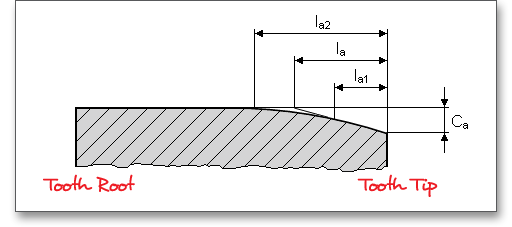
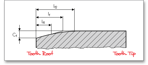
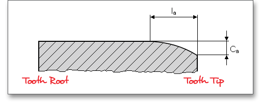
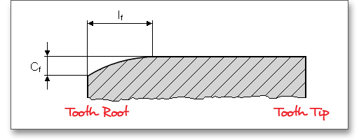
The linear tip and root relief is executed in the eAssistant with a transition rounding from the modified to the unmodified area. You can enter the start and end of the transition rounding in the corresponding input fields. For circular relief, the input of the transition start and transition end is not required.

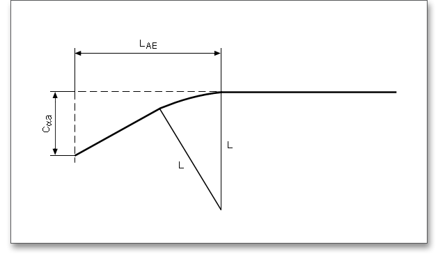
The % button can be used to set the power or torque to be used for the design of the tip relief amount. If the operating conditions are known, the power percentage can be set accordingly. With a click on the calculator button the amount \(C_{a}\) of the tip relief for sun, planet and annulus is then calculated. In case you know the relief length, you can simply enter this value into the input field. In case the length is unknown, select ‘short’ or ‘long’ from the listbox. The eAssistant software determines the relief length automatically. If a diameter is given on the drawing, it is possible to define the diameter. Click the ‘d/l’ button on the right side to switch between the input for diameter or length.
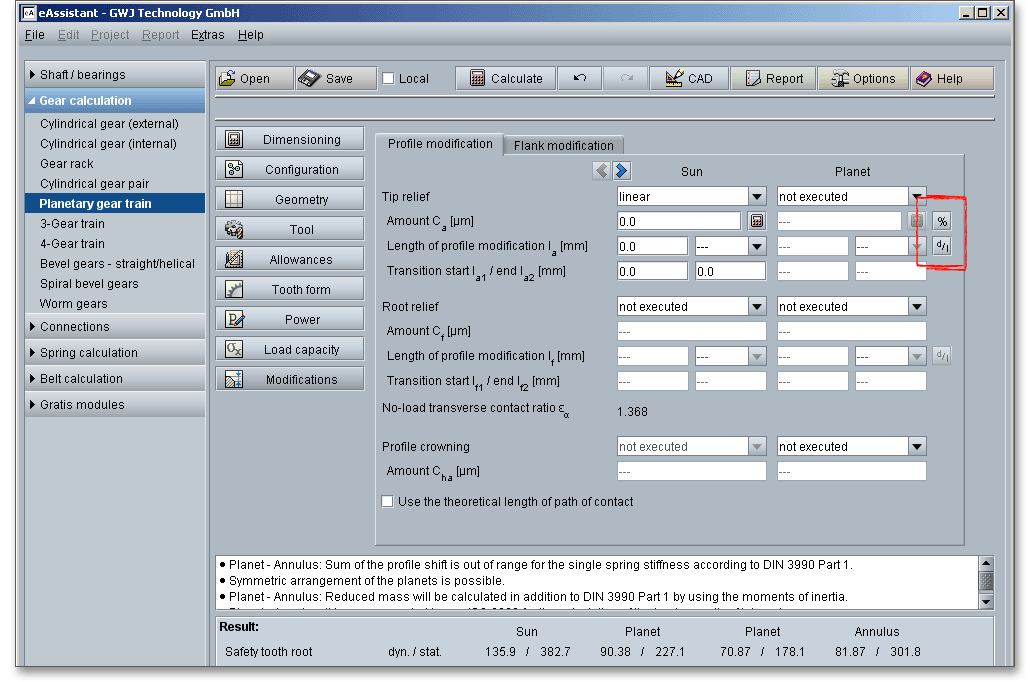
When you enable the checkbox ‘Use theoretical length of path of contact’, then the theoretical path of contact of a gear with a rack is used.
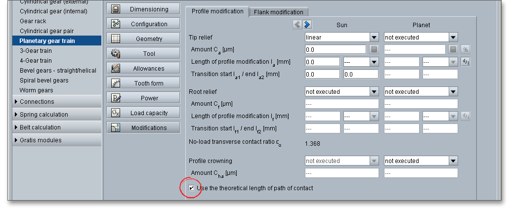
Profile crowning can be seen as a combination of tip relief and root relief. Material is removed from the tip and from the root of the tooth.
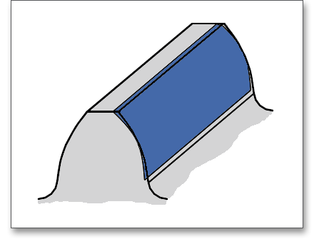
You can select symmetric profile crowning from the listbox and add a value for \(C_{ha}\) to the input field.
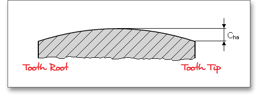
Gear flank modifications are intentional deviations from the theoretical tooth trace. Lead crowning and end relief are typical gear flank modifications and are advantageous for a better load distribution across the facewidth of the gear. Both can compensate for misalignment so that the stresses do not rise at the tooth ends.
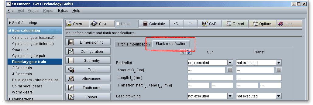
Due to mesh misalignments, an overloading of the tooth ends occurs. Therefore, end relief is used to protect the tooth ends from overloading. Usually, the relief applied is the same at both ends of the teeth. In case crown shaving and crown grinding are not possible, then end relief is recommended.
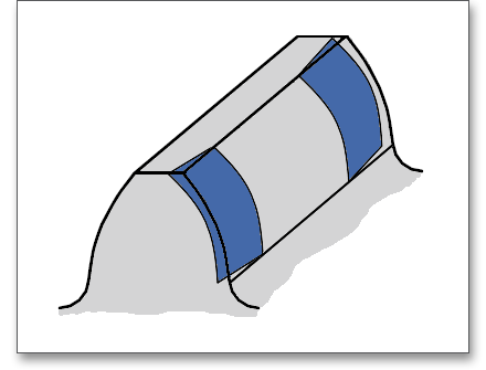
End relief can be applied to both tooth ends or to the left or right end of the tooth.

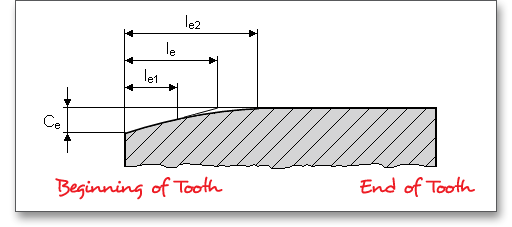
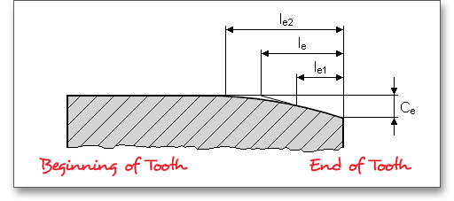
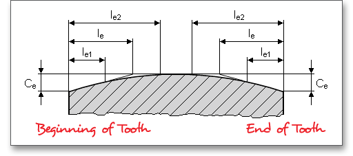
According to DIN 3990 Part 1, the height of end relief is calculated as follows:
For through-hardened gears: \(C_{e} \approx F_{\beta xcv}\) plus a manufacturing tolerance of 5 to 10 \(\mu m\). Thus, by analogy with \(F_{\beta xcv}\) (initial equivalent misalignment) in DIN 3990, \(C_{e}\) should be approximately:
\[C_{e} = f_{sh} + 1.5 \cdot f_{H\beta }\]
For surface hardened and nitrided gears: \(C_{e} \approx 0,5 \cdot F_{\beta x cv}\) plus a manufacturing tolerance of 5 to 10 \(\mu m\).
\(C_{e}\)should be approximately:
\[C_{e} = 0.5 \cdot (f_{sh} + 1.5 \cdot f_{H\beta })\]
When the gears are of such stiff construction that \(f_{sh}\) can for all practical purposes be neglected or when the helices have been modified to compensate deformation, the following is appropriate:
\[C_{e} = f_{H\beta }\]
60% to 70% of the above values is appropriate for very accurate and reliable gears with high tangential velocities.
According to DIN 3990 Part 1, the width (or length) of end relief can be determined as follows:
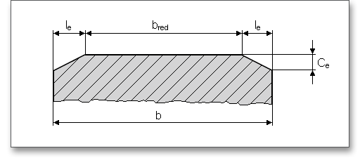
For approximately constant loading and higher tangential velocities:
\(l_{e}\)= smaller of the values \(0.1 \cdot b\) or \(1 \cdot m\)
The following is appropriate for variable loading, low and average speeds:
\[b_{red} = (0.5\ to\ 0.7) \cdot b\]
Lead crowning is a common way of crowning is the so-called lead crowning. This type is employed in order to compensate for manufacturing deviations and load-induced deformations of the gears and in particular to relieve the tooth-end loading.
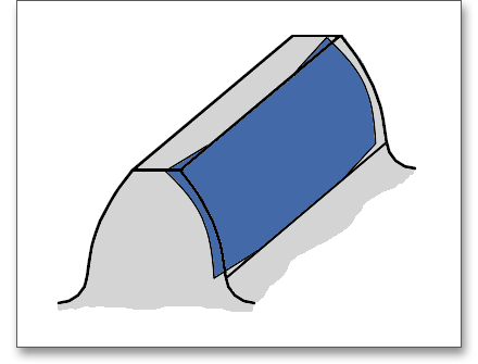
Gears are usually crowned symmetrically about the mid-facewidth and the tooth center is slightly thicker than the tooth edges. The tooth flanks of the gear have a slight outward bulge in its center area. It is possible to select symmetrical and asymmetrical lead crowning from the listbox.
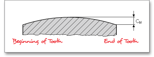
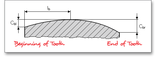
According to DIN 3990 Part 1, the height of lead crowning can be determined as follows:
\[C_{b} = 0.5 \cdot (f_{sh} + 1.5 \cdot f_{H\beta })\]
When the gears are of such stiff construction that \(f_{sh}\) can for all practical purposes be neglected or when the helices have been modified to compensate for deformation at mid-face width, the following value can be substituted:
\[C_{b} = f_{H\beta }\]
Subject to the restriction \(10 \leq C_{b} \leq 25\ \mu m\) plus a manufacturing tolerance of about 5 \(\mu m\), 60% to 70% of the above values are adequate for extremely accurate and reliable high speed gears.
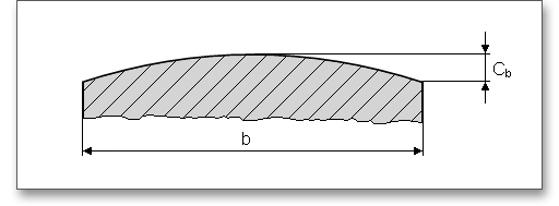
According to DIN 3990, the mesh misalignment \(f_{sh}\) is determined without taking crowning into account. This means that in the calculation of the load capacity (submask \(K_{H\beta }\), ‘no correction’ must be set. With regard to the suggested value of lead crowning calculated according to DIN 3990, it is always a value related to the effective sum of the modifications of pinion and gear in the contact area. This means that the modifications can only be carried out on one gear or divided between the pair. Therefore, the default value calculation for gear 1 and 2 always provides the same value. How this calculated value is then divided, if necessary, is decided by the user. If the value is first suggested for gear 1, it can then be divided between gear 1 and gear 2. This also applies to gear 2. When splitting the crowning amount between both gears, there are various distribution ratios. Often, the following approach is used here:
\[C_{b}^{2} = C_{b1}^{2} + C_{b2}^{2}\]
Therefore, only the value for the pairing is always generated as a default value via the calculator
button.
The design of planetary gear trains requires special attention to meshing interferences in order to avoid gear running noises or damages (e.g., tooth breakage or wear). For external gears, interference takes place between the tip of the tooth of the gear and root fillet area of the mating tooth which can lead to jamming of gear and pinion. The gear mesh of an internal gear pair can be much more difficult than for external gears. Interferences for internal gears occur far more frequently than for external gearings. In case a meshing interference takes place, a warning is displayed in the message window. For internal gears, the general rule is that the minimum number of teeth
\[z_{2} - z_{1} \geq 10\]
should be followed. To avoid meshing interferences between the gear shaper cutter and internal gear, the minimum number of teeth needs to be increased. The following meshing interferences can appear in the calculation module:
Please note: Meshing interferences may be eliminated or minimized by tip easing on the internal gear or on the
pinion by increasing the pressure angle or helix angle.
When the tooth tip of the internal gear interferes the root fillet radius, then a tooth root meshing interference on
the pinion occurs.
When the tooth tip of the pinion interferes the root fillet radius of the internal gear, then a tooth root meshing
interference occurs.
When shaper cutter and internal gear are in mesh, the generation meshing interference occurs due to
tool cutter action in generating teeth with low numbers of teeth. Because of this interference there
is a loss of the involute profile at the tooth tip. The term of the mesh and the load capacity are
decreased.
The tooth crest meshing interference may occur when the tooth crests of pinion and internal gear overlap during
the hobbing process outside of the plane of action. For number of teeth differences of \(\left |z_{2}\right | - z_{1} < 10\) this meshing interference
may occur frequently. For the generation of internal gears with gear shaper cutter, tooth crest meshing
interference appears.
Please Note: Meshing interference can be avoided by changing the number of teeth and by a negative profile
shift.
If the chosen gear shaper cutter is too large and the teeth of the internal gear are cut off in the feed direction, a
feed meshing interference occurs.
Please Note: If the sum of the profile shift is decreased, feed meshing interferences can be avoided. It is also
possible to adjust the number of teeth of the gear shaper cutter.
When internal gearsets have a too small difference between the number of teeth in the pinion and the number of
teeth in the gear, there may be interference between the tips of the teeth. The interference is most apt to occur
as the pinion is moved radially into mesh with the gear. It is possible to get around the radial-interference
difficulty by assembling the set by an axial movement of the pinion.
Please Note: A radial assembly interference can be removed by decreasing the profile shift coefficients and addendum coefficient of pinion and internal gear.
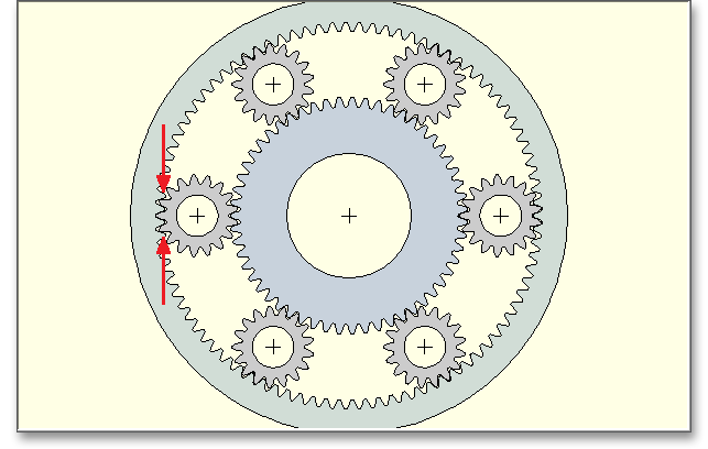
If there are no special requirements for the planetary gear train, then the design of the external gear is not
different from the design of the stationary gear. Small gears are ideal for a more compact design manufactured
as solid gears. For higher ratios, the gears are made in one piece with a shaft. Disc wheels are often used for
larger gears. Internal gears for high-duty gearings should be supported on both sides, for light loads overhung
gears can be used.
The installation of bearings is often difficult because of the small space in the planetary gear. It is possible to
leave the central pinion unsupported. The torque is transmitted by toothed couplings. The elimination of the
bearing gives the advantage that the efficiency is increased. An additional device for the lubrication
of the bearing is no longer necessary. The planet gear can be mounted on the planet gear pin
which is firmly connected to the carrier. However, the pin can also be supported on the carrier
and can be firmly connected to the planet gear. Plain bearings and rolling bearings are generally
used.
The planetary carrier of a gear train can have a split and non-split design. Split types consists of elements made
from sheets or rolled steel products. Planetary carriers for higher loads are cast. Non-split types are torsionally
very stiff and resistant to thermal expansion. The planet gear pin can be rotatably supported or can be firmly
clamped. If the pins are connected to the carrier, pins and screws must be firmly tightened and the entire gear
train must be in safe working order.
According to economical aspects, the housing of a planetary gear train can be cast or welded. Welded housings are often used for special gearboxes and gearings with low mass. In the case of batch production, cast housings are commonly used. For larger gears with low mass, double-walled, welded steel housings are used.
If only a few input data are available, such as input speed, power and transmission ratio, the software can provide corresponding suggestions for number of teeth and module at the push of a button.
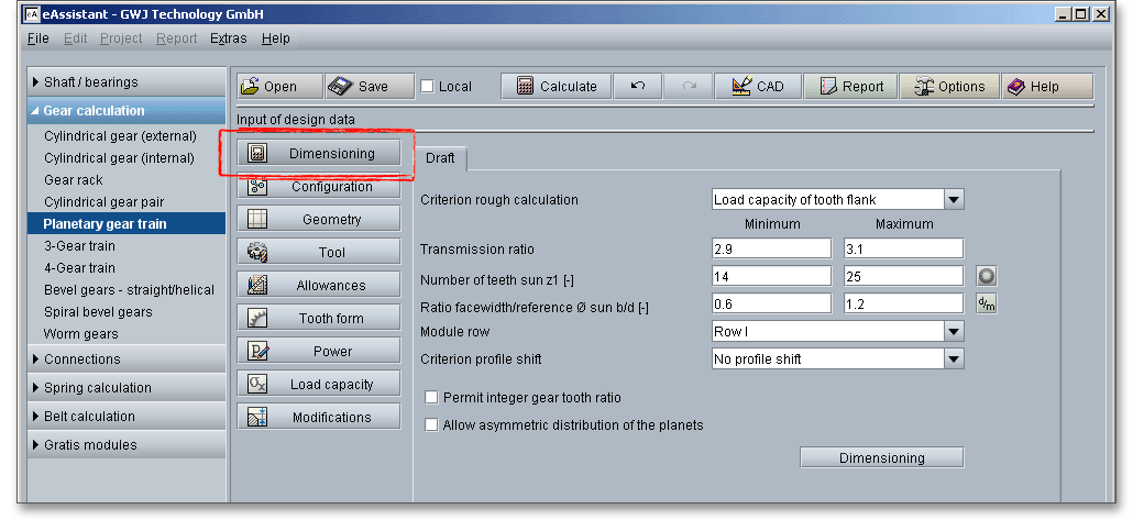
Before you start with the design, the load capacity must be activated, otherwise the design is not possible. You can specify the material for the sun, planet or annulus or adjust the application factor and the lubricant.
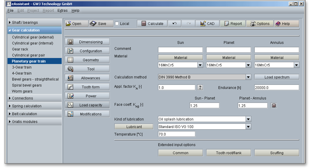
Furthermore, the power data, allowances, tool data as well as the configuration can be modified via the
corresponding main masks before the design layout. If you have defined all settings for the pre-design, then go
to the main mask ‘Dimensioning’.
However, before you continue with the further design data, please take a look at the ‘ Options’ menu first. In this menu, the minimum safeties for the root and flank load capacity are stored. These specified minimum safety factors are taken into account in the same way during design.
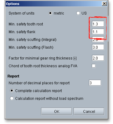
Please Note: For standard industrial applications, the standard values for minimum safety of 1.3 for the tooth
root load capacity and 1.1 for the flank load capacity can be adopted in this way. For applications with a large
damage effects or where personal injury may occur, larger minimum safeties should be selected. For a
smaller module range (< 1), for example in precision engineering, smaller minimum safeties are
suitable.
The remaining entries are now completed in the main screen for the design layout. A specific range can always be specified for the transmission ratio, number of teeth of sun/annulus and ratio of facewidth/reference diameter sun. The corresponding buttons can be used to switch between the number of teeth of sun and annulus as well as the facewidth/reference diameter ratio and the facewidth/normal module ratio.
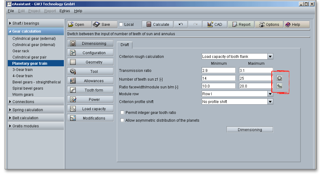
When you have made all the entries, click on the button ‘Dimensioning’. Now the software calculates all possible
variants and a list for possible solutions is displayed afterwards.
When displaying the found suggestions, you can re-sort the list by clicking on the respective column heading. If you want to sort the column in reverse order, click the column heading again. Select a suggestion from the list and click the ‘OK’ button. The selected values will now be entered into the software, giving you an initial calculation suggestion that can then be refined and processed further. This is a quick way to find a usable solution that you can start with. Later you can modify the design according to your own criteria.
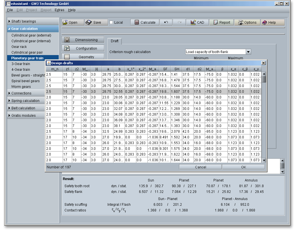
The calculation module provides a message window. This message window displays detailed information, helpful hints or warnings about problems. One of the main benefits of the program is that the software provides suggestions for correcting errors during the data input. If you check the message window carefully for any errors or warnings and follow the hints, you are able to find a solution to quickly resolve calculation problems.

The quick info tooltip provides additional information about all input fields and buttons. Move the mouse pointer over the input field or button, then you will get the additional information. This information will be displayed in the quick info line.

All results will be calculated during every input and will be displayed in the result panel. A recalculation occurs after every data input. Any changes that are made to the user interface take effect immediately. In case a minimum safety is not fulfilled, the result will be marked red. Press the Enter key or move to the next input field to complete the input. Alternatively, use the Tab key to jump from field to field or click the ‘Calculate’ button after every input. Your entries will be also confirmed and the calculation results will displayed automatically.

After the completion of your calculation, you can create a calculation report. Click on the ‘Report’ button.

The calculation report contains a table of contents. You can navigate through the report via the table of contents that provides links to the input values, results and figures. The report is available in HTML and PDF format. Calculation reports, saved in HTML format, can be opened in a web browser or in Word for Windows.
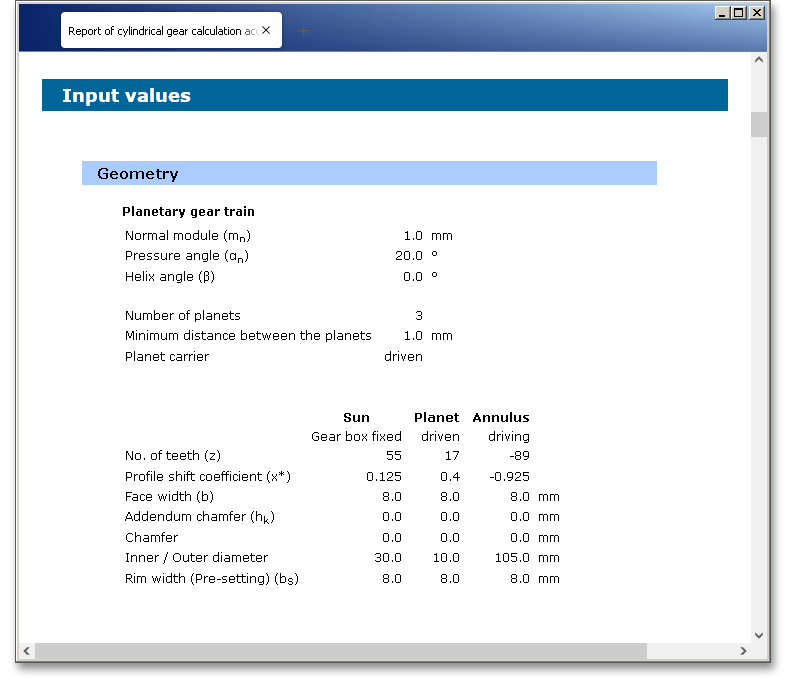
You may also print or save the calculation report:
When the calculation is finished, it is easy to save the calculation. You can save your calculation either to the eAssistant server or to your computer. Click on the button ‘Save’.

Before you can save the calculation to your computer, you need to activate the checkbox ‘Local’ in the calculation module. A standard Windows dialog for saving files will appear. Now you will be able to save the calculation to your computer.
In case you do not activate the option in order to save your files locally, then a new window is opened and you can save the calculation to the eAssistant server. Please enter a name into the input field ‘Filename’ and click on the button ‘Save’.
The ‘Undo’ button allows you to reset your inputs to an older state. The ‘Redo’ button reverses the undo.

The top menu bar of the eAssistant software provides the button ‘CAD’.

The eAssistant plugin for various CAD systems (e.g., SOLIDWORKS, Solid Edge, Autodesk Inventor) enables
you to combine calculation and design very easily. On the basis of the eAssistant calculation, you can generate
spur gears in a 2D DXF format or create as a 3D part within seconds.
Click on the menu item ‘CAD \(\Rightarrow \) DXF Output’. Now you are able to create the accurate tooth form of any involute gearing in the 2D DXF format. Use the various settings for the DXF output.
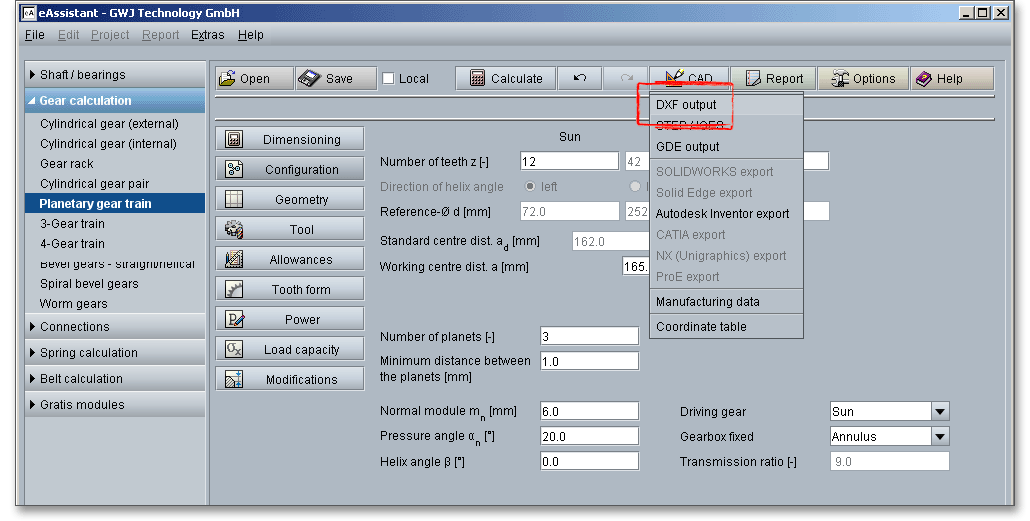
For the DXF output the following options are possible:
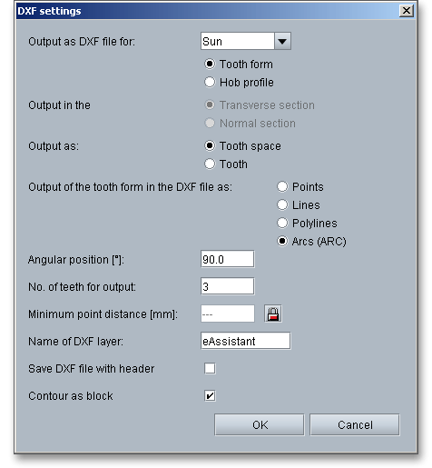
When you have defined all settings, then click on the button ‘OK’. A standard Windows dialog is opened to save
the file.
Now you can save the DXF file to your computer. Enter a name for the file and click on the button ‘Save’. It is not necessary to specify the file extension. The file is identified automatically.
Using this function allows to create the geometry of cylindrical gears as 3D CAD models in STEP or IGES format. STEP as well as IGES are two standardised neutral file formats for CAD models. Almost every 3D CAD system can import STEP files.

The settings menu for the STEP and IGES output has a few different functions and allows to adjust the export options as needed. The geometry can be generated as a solid model with one or all teeth or as a surface model of the tooth space geometry. When exporting to a CAD system, you can also set the level of accuracy to a desired value.
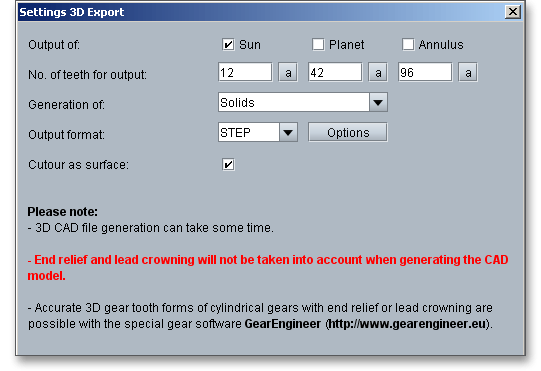
With the integration of the standardised GDE format into the modules for gears and involute splines, eAssistant takes a step closer to a seamless data workflow. GDE stands for Gear Data Exchange. This format, which is defined in VDI/VDE guideline 2610, is already supported by many measuring machine manufacturers. With the GDE format, geometries of cylindrical gears and involute splines can be loaded directly from the software into the measuring machine. It only takes a few clicks to create a measuring program. This avoids transmission errors and allows to work with standard measuring instructions.

The eAssistant plugin for various CAD systems (e.g., SOLIDWORKS, Solid Edge, Autodesk Inventor) enables you to combine calculation and design very easily and fast. Based on your eAssistant calculation, you can generate spur and helical gears as a 3D part within seconds. A single menu pick in the eAssistant software transfers the eAssistant calculation data to the CAD system. Based on these parameters, the automatic creation of a 3D parametric model starts in the CAD system. Allowances, addendum chamfer and profile shift are taken into consideration.

The CAD model stores all features and dimensions as design parameters. The eAssistant calculation is linked
and associated to the part and can be opened at any time throughout the entire design phase.
This is also possible if one part contains different calculations. Click the button ‘CAD’ and select
the CAD plugin. Open the CAD system and start the generation by clicking the integrated button
‘eAssistant’.
Please note: First you need to download and install the right CAD plugin for your CAD system. The plugin is
available on our web site www.eAssistant.eu. After installation, an integrated button called ‘eAssistant’ appears
in the CAD system.
With just one click, the design table with all manufacturing details can be placed on the drawing. The
appearance and size of that table is individually configurable. There is no need to manually add all design table
parameters to the drawing. For further information, please visit our web site www.eAssistant.eu or read the
CAD plugin manual.
The button ‘CAD \(\Rightarrow \) Manufacturing data’ allows to save the manufacturing data to a text file.
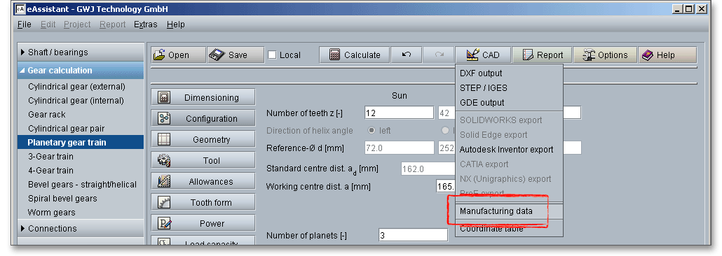
The gear tooth form geometry of a tooth space can be exported as a coordinate text file in transverse section as well as in normal section.
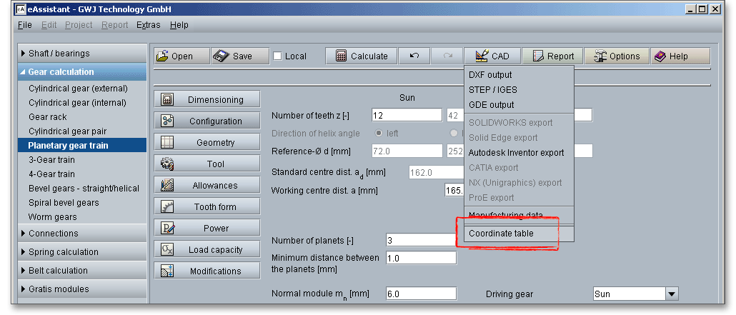
Click on the button ‘Options’ in the top menu bar of the eAssistant software to change some general settings.

