Please login with your username and your password. To start the calculation module for involute splines, please click the menu item ‘Connections’ on the left side and then select ‘Involute splines’.

This eAssistant module allows for the calculation of splined connection with involute splines according to DIN
5480, DIN 5482, ISO 4156, ANSI B92.2M, ANSI B92.1 as well as the French standard NF E22-141. The
calculation of the strength is based on Niemann ‘Maschinenelemente 1‘, 2001. Involute splines are used to
transmit torque from a shaft to a gear hub where external gear teeth on the shaft engage an equal number of
internal teeth in the hub. Involute splines offer several interesting advantages: Involute splines can be produced
by the same manufacturing processes and machines as ordinary gears. No special machines are
required in order to produce involute splines. Involute splines are the predominant form because they
are stronger than straight sided splines and are easier to cut and they are used to transmit larger
torques.
DIN 5480 applies to splined connections with involute splines based on reference diameters for connecting hubs and shafts either with a removable connection, a sliding fit or a permanent fit. It lays down the following principles:
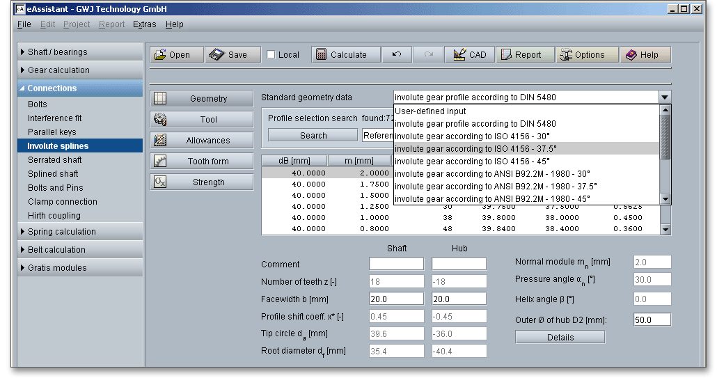
Select the appropriate standard from the listbox ‘Standard geometry data’. DIN 5480 applies for involute splines in the module range 0,5 to 10 with a number of teeth ranging from 6 to 82 and a pressure angle of \(30^{\circ }\). The DIN 5480 series of standards is limited to splines with a pressure angle of \(30^{\circ }\). Pressure angles of \(37.5^{\circ }\) and \(45^{\circ }\) are covered by ISO 4156. In addition to DIN 5480 and ISO 4156, it is possible to select DIN 5482, ANSI B92.2M, ANSI B92.1 as well as the French standard NF E22-141 from the listbox.
Please note: In the French standard NF E22-141, the module is divided into two series - Primary and
Secondary Series. The Primary Series is the recommended preferred series and is available in the
eAssistant
Based on the selected profile, number of teeth, profile shift coefficient, normal module and pressure angle will be set and the tip circle diameter and the root diameter are determined. You can refine the profile geometry selection by including specific parameters to find the right profile quicker. The following parameters can be defined for a certain range:

Please enter your values into the input fields ‘from’ and ‘to’ and click the button ‘Search’ to start the profile selection search. The number of found profiles will be displayed. The number of profiles will be reduced and you can select the profiles directly from the list. If you have already entered values into the input fields and want to change your entry for any reason, please delete the value and click into another input field or use the Tab key. The option ‘Any’ is used again in the input field.

You can sort the selection list in the database by clicking on the column header. To sort the profiles in reverse order, click on the column header again. A black arrow appears. The arrow makes the orientation much easier for you.

When you select a profile from the table, parameters (e.g., number of teeth, profile shift coeffcient, module and pressure angle) will be displayed.

You can add a description or a short comment to shaft and hub. The notes will appear later in the calculation report.
External gear teeth on the shaft engage an equal number of internal teeth in the hub. According to DIN 3960, the number of teeth of internal gears is negative. This leads to negative signs for all hub diameters.
In accordance with DIN 5480, the profile shift for the shaft is kept within the range \(-0.05 \cdot m\) and \(+0.45 \cdot m\) and for the hub within
the range \(+0.05 \cdot m\) and \(-0.45 \cdot m\).
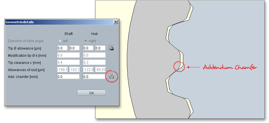
Click the button ‘Details’ in order to add more inputs for the geometry. A new window is opened and you can modify the tip diameter allowance by clicking the ‘Lock’ button. Add an addendum chamfer or tip radius for shaft and hub.
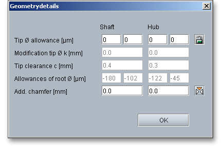
The tip diameter allowances are not determined by default. Therefore, all input values are specified with ‘0’.
Click the ‘Lock’ button and all input values will be disabled and the allowances are determined in
accordance with DIN. Click the ‘Lock’ button again to enable the input field and to add your own
value.
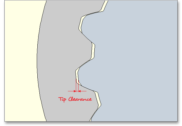
Clearance \(c\) is the distance between the root circle of a gear and the addendum circle of its mate. A certain clearance between the gears is necessary for a smooth operation without jamming. The diameters of the tip and root circles of the shaft differ from the respective diameters of the hub by at least the tip clearance \(c\).
The tooth ends of a gear are often rounded or chamfered. A chamfer is a small angled surface added on the end of a shaft along an edge. For the calculation you can consider the addendum chamfer. Meshing interferences can be removed by the addendum chamfer.
As an alternative to the addendum chamfer, a tip corner radius can be specified. This can be defined either as a radial amount or directly as a radius. The selection is marked by the colored arrow. The radius is entered directly for the tip radius, the radial amount is entered for the tip radius (Rad.). If you enter the tip radius directly as a value, you will receive the corresponding radial amount in the calculation report. In the case of tip corner radius or addendum chamfer, the tip form diameter is smaller than the tip circle diameter by twice the radial amount \(h_{K}\).
In case you cannot find the right profile you are looking for in our extensive database, then simply define your individual profile. Activate the option ‘User defined input’ from the listbox. If you select this option, the input fields will be enabled, so that you can enter your own input values.

The tip circle diameter \(d_{a}\) is automatically determined according to the selected standard, for example in accordance with DIN 5480. In case the option ‘User defined input’ is enabled, then a ‘Lock’ button appears next to the input field. Click the ‘Lock’ button in order to activate the input field and to modify the tip circle diameter. Please note that the tip diameter has an influence on the modification of the tip diameter. Click on the button again to disable the input field. The value is determined again according to DIN. In case you use special tools, the tip circle diameter can be modified by a tool customization.

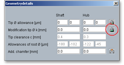
The modification of the tip diameter \(k\) is automatically determined by the program that a sufficient tip clearance is available. For external gears the modification of the tip diameter is \(k \le 0\), for internal gears, the value is often set to \(k = 0\) in order to avoid meshing interferences. Click on the ‘Lock’ button to enable the input field and enter your own value. Such a modification of the tip diameter has an effect on the tip diameter.
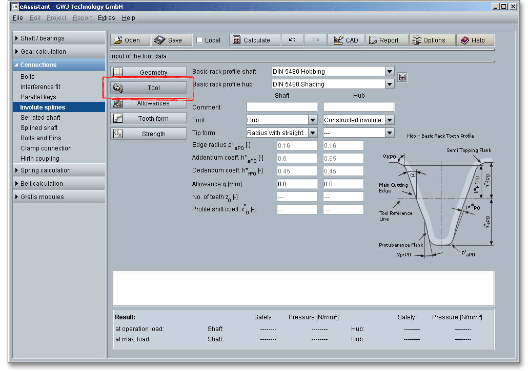
A basic rack profile for the shaft or hub according to DIN, ISO or ANSI can be selected from a listbox or can be defined individually. Involute splines can be produced by the same manufacturing processes and machines as ordinary gears. A machining allowance can be taken into consideration. Usually, external splines are cut by hobbing, rolling or shaping and the internal ones are produced either by broaching or shaping in a gear shaper.
Please note: You can add a description or a short comment to shaft and hub. The notes will appear later in the
calculation report.
Select either the tool ‘Hob’ or ‘Gear shaper cutter’ by clicking the listbox. A ‘Constructed involute’ is also available.

The hobbing is the most widely used method of cutting gear teeth. The cutter, called the hob, is like a worm. All gears are cut by feeding the hob across the facewidth of the gear. According to DIN 5480, for any number of teeth of one module size only one cutter is required.
A gear cutting method in which the cutting tool is shaped like a pinion. The shaper cuts while traversing across the facewidth and rolling with the gear blank at the same time. According to DIN 5480, several gear shaper cutter of different numbers of teeth are standardized for each module. These apply for:
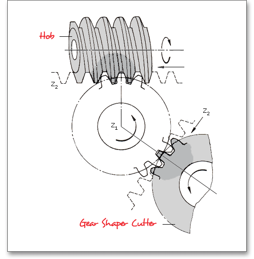
In addition to the hob and the gear shaper cutter, you can also select the entry ‘Constructed involute’ as a tool. In case internal gears cannot be shaped with a gear shaper cutter, the tooth form calculation is still possible by using the constructed involute. This specifically applies for applications in the precision mechanics. This method allows a generation of the tooth form with a constant root fillet radius.

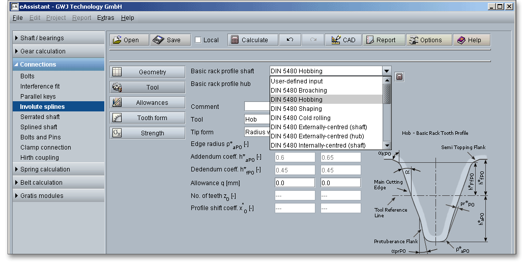
The tool standard basic rack profile is the counter profile of the standard basic rack tooth profile. The listbox provides the following tool standard basic rack tooth profiles:
Hubs are often made by broaching. Broaching is a machining process that uses a toothed tool, called a broach,
to remove material. Broaches are tools adapted for a single operation. The broach usually only moves linearly
against a surface of the workpiece. The process depends on the type of broaching being performed.
Small internal gears can be cut in one pass. Large internal gears can be made by using a surface
type of broach to make several teeth at a pass. Broaching is a very accurate method and a rapid
operation.
The following applies for broached involute splines:
According to DIN 5480 the following applies:
Hobbing is a nearly universal process which can be used to manufacture spur and helical gears of all types and
it is the most widely used method of cutting gear teeth. The tool used in this process is a hob. A very high
degree of tooth-spacing accuracy can be obtained with hobbing. With regard to accuracy, hobbing is superior to
the other cutting processes. A wide variety of sizes and kinds of hobbing machines are used. The
rotating hob has a series of rack teeth arranged in a spiral around the outside of a cylinder, so it
cuts several gear teeth at one time. To generate the full width of the gear, the hob slowly traverses
the face of the gear as it rotates. Thus, the hob has a basic rotary motion and an unidirectional
traverse at right angles. Both movements are relatively simple to effect, resulting in a very accurate
process.
The following applies for hobbed involute splines:
Gear shaping is a continuous indexing gear cuttin process in which the cutting tool is shaped like a pinion. The
cutter reciprocates while it and the gear blank are rotated together at the angular-velocity ratio corresponding to
the number of teeth on the cutter and the gear. The teeth on the gear cutter are appropriately relieved to form
cutting edges on one face. Although the shaping process is not suitable for the direct cutting of
ultra-precision gears and generally is not as highly rated as hobbing, it can produce precision quality
gears. Usually it is a more rapid process than hobbing. Two outstanding features of shaping involve
shouldered and internal gears. For internal gears, the shaping process is the only basic method of tooth
generation.
The following applies for shaped involute splines:
The rolling process is mainly applicable to involute splines and it is a highly efficient manufacturing process.
Rolling is a forming process where a workpiece lies between two cylindrical rollers provided with teeth.
Cold-rolling is very rapid and it produces a very smooth surface. This method improves the surface conditions
and holds tighter tolerances. There are three major methods of rolling: longitudinal, transverse and rotary
rolling and DIN 5480 describes longitudinal and transverse rolling. In longitudinal rolling, the metal is
deformed by rolls, usually parallel to each other that rotate in opposite directions. In transverse
rolling, the metal is subjected to rotational motion relative to its axis and is worked in the transverse
direction.
The following applies for cold-rolled involute splines:
Click ‘user defined input’ from the listbox in order to define your own basic rack profile. If you select ‘user defined input’, then the input fields for the edge radius, the addendum coefficient and the dedendum coefficient are activated. Now you can modify the basic rack profile.

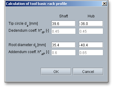
In case you use special tools, the eAssistant software offers an easy and comfortable solution. The basic rack profile can be determined by clicking the ‘Calculator’ button.

Here you can change the tip circle and the root diameter for shaft and hub. Confirm your entries with the button ‘OK’. The listbox for the basic rack profiles displays then ‘User defined input’. The modification of the tip diameter is set to ‘0’.
You can consider an allowance for the tooth flank. The tool provides an allowance \(q\) on the flank and/or root for the pre-cutting tool. The allowance is the smallest distance between the involutes and the pre-machining having the same root diameter. In case you select the tool basic rack profile with protuberance, the allowance refers to the tooth flank. The maximum machining allowances can be grouped as follows:
| Maximum Machining Allowances1
| |
| Allowance per Tooth Flank | Manufacturing Process |
| \(<\) 0.05 (0.10) mm | Finishing operation by cold rolling, gear shaving, honing, lapping |
| 0.05 to 0.5 (1.5) mm | Grinding, profile grinding, (honing) |
| \(>\) 0.5 mm, pre-cutting | Primary shaping, forming, cutting with geometrically determined edges except shaving, grinding and profile grinding in special cases |
| 1 from: Linke, H.: Stirnradverzahnung Berechnung Werkstoffe Fertigung, Carl Hanser
Verlag, Muenchen, Wien, 1996, p. 638
| |
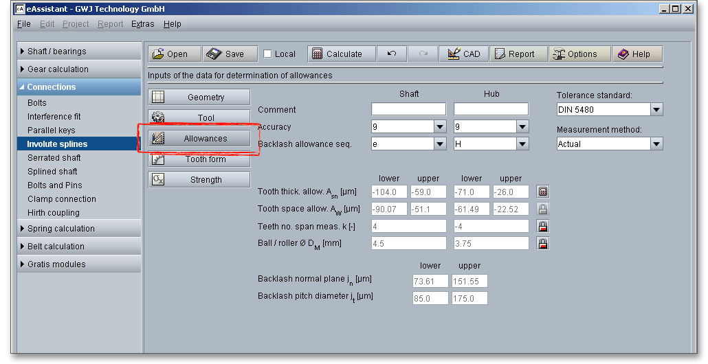
In order to define the tolerances, gear accuracy and allowance sequence can be selected from the listbox. All permitted deviations and tooth thickness allowances will be automatically determined. Similar to the tolerance system in DIN 3961, DIN 5480 also provides a tolerance system. The tolerance system refers to the pairing nominal spacewidth and nominal tooth thickness.
Please note: You can add a description or a short comment to shaft and hub. The notes will appear later in the
calculation report.
The choice of the right toothing quality is determined by economical aspects depending upon the intended purpose and manufacturing process. In all fields of gearing, the control of gear accuracy is essential. Several classes or grades of accuracy can be set. 12 grades (12 to 1) are defined according to DIN standards. Accuracy grade ‘5’ describes the highest possible accuracy, ‘12’ a very low accuracy.

Positive and negative minimum fit clearances can be designed using the spacewidth deviation \(A_{e}\) and the tooth thickness deviation \(A_{s}\). The magnitudes of the deviations are identified by lower case characters and can be selected individually for the hub and the shaft from the listbox. There are six deviations from F to M for hubs and 18 deviations from v to a for shafts. Interference fits, transition fits and clearance fits can be specified by using the allowance sequence.

DIN 5480 provides deviation and tolerance combinations in order to achieve interference fits, transition fits and clearance fits.
| Type of Fit | ||||||||
| Hub | Shaft | |||||||
| Rough interference fit | 9H | 9v | ||||||
| Fine interference fit | 7H | 8H | 7p | 8s | ||||
| Rough transition fit | 9H | 9p | ||||||
| Fine transition fit | 7H | 8H | 8n | |||||
| Rough clearance fit | 9H | 9g | 9e | 9d | 10c | 11a | ||
| Fine clearance fit | 7H | 8H | 7h | 7g | 8f | |||
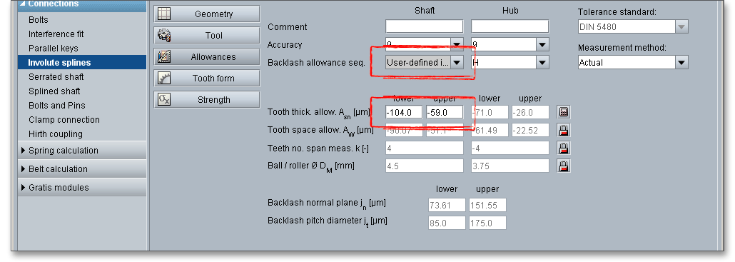
If you select the entry ‘user defined input’ from the listbox, the input field for the tooth thickness allowances is enabled and you can define your individual values. If you select the entry ‘effective’ from the listbox ‘Measurement method’, you will notice, that the ‘Lock’ button next to the input field for the tooth space allowances is also enabled.
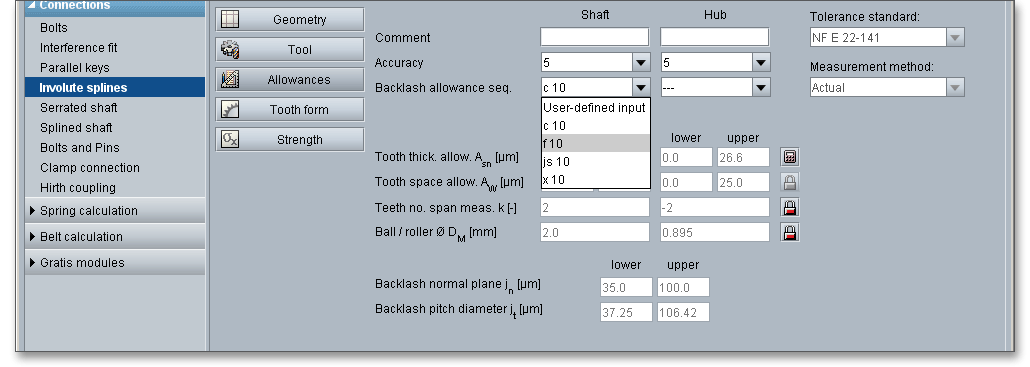
The French standard NF E22-141 provides the following fits for the shaft:
The fit and the centring accuracy are determined by the deviations of the spacewidths and thicknesses as well as by the achieved or defined tolerances. The eAssistant offers the possibility to specify the tooth thickness allowances based on measured data or given test dimensions. Two different dimensions for the tooth thickness can be selected - the actual and the effective tooth thickness. The different dimensions will then be considered during calculation and output of the gear tooth form as well as for the determination of the test dimensions, such as number of teeth measured for facewidth measurement or diametrical measurement over balls or pins. Select ‘Effective’ from the listbox and click on the ‘Calculator’ button.
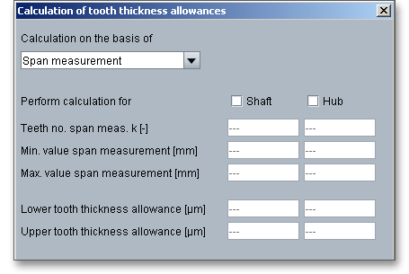
Activate shaft and hub and enter the input values. Confirm with the button ‘OK’. The ‘Lock’ button next to
the input field for the tooth space allowances is enabled. Now you can change the tooth space
allowances.
According to DIN 5480, th actual tolerance provides for the wear-dependent change of tool dimensions, the
infeed accuracy of machine tools and dimension deviations in heat treatment. In the data field of the workpiece
drawing, it is indicated as the actual tolerance limit and as the reference mark actual Ref. Since it is difficult to
measure tooth thickness and space widths directly, they are converted to dimensions across and between
measuring circles and are entered in this form into the data field. In practice, measuring balls or measuring pins
are used as measuring circles.
According to DIN 5480, the effective tolerance for fitted splined connections is shown separately. This is necessary because the fit is generated for all left and right flanks of all teeth. The tooth flanks are subject to individual deviations from the profile, the tooth trace and the pitch. These deviations reduce the fit clearance of a fitted splined connection so severely that provision must be made for this reducing effect. In hubs, the superposition of all individual deviations leads to an effective spacewidth that is smaller than the actual space that can be measured.
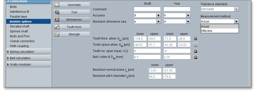
The tooth space allowance \(A_{W}\) is the difference between the actual dimension and the nominal dimension of the span measurement \(W{_k}\). The actual measurement of the span measurement gets smaller for external gears by negative allowances for a zero-backlash assembly. The upper and lower tooth space allowance are displayed as well. For an own input of the tooth thickness allowances, the tooth space allowances can be defined as well. The ‘Lock’ button next to the input field of the tooth space allowances is enabled. Therefore, you can change the tooth space allowances.

The calculation program determines the number of teeth for the span measurement (number of teeth across the span measurement has to be gauged). By using the ‘Lock’ button you are able to activate the input field and you can enter your own input value. If you click the button again, the previous input value appears.

The tooth thickness is often checked by measurement over balls \(M_{dK}\) or pins \(M_{dR}\). The pins or balls are placed in diametrically opposite tooth gaps (even number of teeth) or nearest to it (odd number of teeth). The measurement over pins is only used for spur gears and external helical gears. The eAssistant software already specifies the diameter of ball or pin for the test dimensions. Enable the input field by clicking the ‘Lock’ button. Enter your own input value for the diameter. If you click on the button once again, the previous input value appears.

The general purpose of backlash is to prevent gears from jamming. The backlashes are automatically determined.
In flank-centred connections, the flanks of the teeth serve to transmit the forces as well as to centre the parts. The difference between the spacewidth and the tooth thickness determines the backlash pitch diameter. The backlash pitch diameter is automatically determined by the calculation module. For spacewidths of hubs and tooth thicknesses of shafts, DIN 5480 provides deviation series and tolerances based on the nominal dimensions. The deviation series permits the definition of clearance fits, transitions fits and interference fits. The tolerance classes define the manufacturing tolerances.

A special highlight of this calculation module is the presentation of the accurate gear tooth form with an animation and simulation of the tooth mesh. For the presentation you can select the lower, upper and mean allowances for the tooth thickness, tip diameter and centre distance.
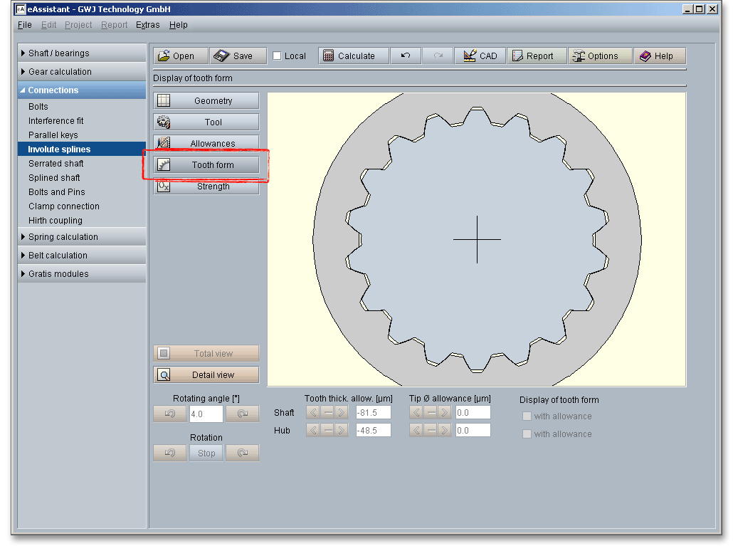
Click on the ‘Tooth form’ button to represent the entire shaft-hub connection.
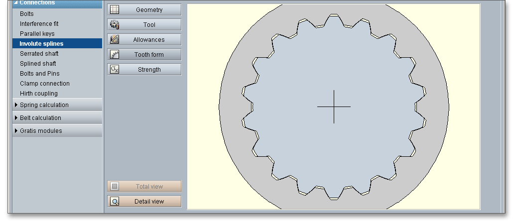
Click on the ‘Detail view’ button. You get a larger representation of the mesh. The representation of the mesh allows you to look at the tooth thickness allowances, the tip diameter and centre distance allowances as well the tooth mesh and to check the influence of these values. The tooth form mask provides various functions. Click on the ‘Total view’ button to obtain an entire view of the shaft-hub connection.
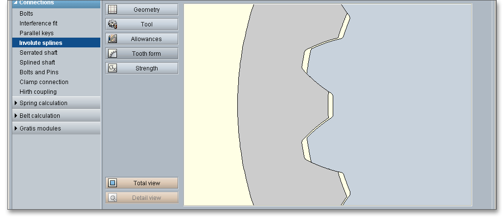
Please note: Please keep in mind that all values are later taken over to the DXF output and CAD generation. In
case you change the tooth thickness allowance or the centre distance allowance in the tooth form mask, then
the last modification is taken over to the DXF output. The section ‘CAD button’ contains some helpful information
on this function.
Enter an rotating angle for the rotation of the involute spline.

|
| Rotation of the shaft counter-clockwise |
|
| Rotation of the shaft clockwise |
When you click on one of the two arrows, a continuous rotation of the shaft occurs.

|
| Continuous rotation of the shaft counter-clockwise |
|
| Continuous rotation of the shaft clockwise |
|
| The rotation is stopped. |
Click on the ‘Detail view’ button and the tooth mesh is represented in detail. Now you can change the tooth thickness allowance, that is already given in the main mask for the ‘Allowances’, within the tolerance limit. All changes are displayed immediately. For the representation of the tooth mesh, select the lower, upper and mean tooth thickness allowances for shaft and hub.

Both arrows indicate the lower and upper allowance. The active input is grayed out and disabled. Click on the left arrow and you will get the representation for the lower tooth thickness allowance. The right arrow shows the representation for the upper tooth thickness allowance.
At the first start of the tooth form, you will get the mean tooth thickness allowance as a standard feature. The tooth thickness allowances can be defined between the lower and upper allowance.

Please note: In case you have specified the lower and upper tooth thickness allowance for shaft and hub in the
input mask ‘Allowances’ by using the ‘Calculator’ button, then the manually defined values appear here as lower
and upper tooth thickness allowance.
Click the ‘Detail view’ button and the tooth mesh is represented in detail. Now you can change the tip diameter allowance, that is already given in the main mask for the ‘Geometry’, within the tolerance limit. All changes are displayed immediately. For the representation of the tooth mesh, select the lower, upper and mean tip diameter allowances for shaft and hub.
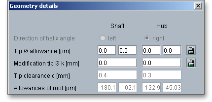
Both arrows indicate the lower and upper allowance. The active input is grayed out and disabled. Click on the left arrow and you will get the representation for the lower tip diameter allowance. The right arrow shows the representation for the upper tip diameter allowance. The middle button displays the mean tip diameter allowance. At the first start of the tooth form, you will get the mean tip diameter allowance. The tip diameter allowances can be defined between the lower and upper allowance.

Please note: In case you have specified the lower and upper tip diameter allowance for shaft and hub in the
input mask ‘Geometry’ by using the ‘Lock’ button, then the manually defined values appear here as lower and
upper tip diameter allowance.
The eAssistant software calculates the strength of involute splines according to Niemann ‘Maschinenelemente‘ Vol. 1, 2001 in order to determine the influences of the load due to torque and load peaks. Click the listbox ‘Calculation method’ and select ‘According to Niemann’ to activate the strength calculation. The permissible pressure is determined from the material properties as well as the surface pressure and safeties for operating load and maximum load of shaft and hub. The load distribution factor \(K_{\lambda }\) is determined for a different load input and load output according to DIN 6892.
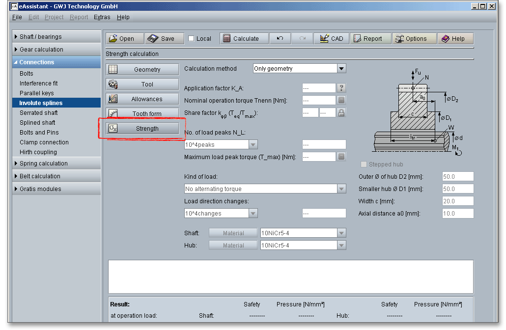
The application factor \(K_{A}\) evaluates the external dynamic forces that affect the gearing. These additional forces are largely dependent on the characteristics of the driving and driven machines as well as the masses and stiffness of the system, including shafts and couplings used in service. The following table gives some values according to DIN 3990. You will find a ‘Question mark’ button next to the input field. Click on this button to open the table.
| Application Factors \(K_{A}\) According to DIN 3990-1: 1987-12
| ||||
| Working Characteristics | Working Characteristics of the Driven Machine | |||
| of the Driving Machine | Uniform | Light shocks | Moderate shocks | Heavy shocks |
| Uniform | 1.0 | 1.25 | 1.5 | 1.75 |
| Light shocks | 1.1 | 1.35 | 1.6 | 1.85 |
| Moderate shocks | 1.25 | 1.5 | 1.75 | 2.0 |
| Heavy shocks | 1.5 | 1.75 | 2.0 | 2.25 or higher |
| Examples for Driving Machines with Various Working Characteristics
| |
| According to DIN 3990-1: 1987-12 | |
| Working | Characteristics |
| Uniform | Electric motor (e.g. d.c. motor), steam or gas turbine with uniform operation1 and small rarely occurring starting torques |
| Light shocks | Steam turbine, gas turbine, hydraulic or electric motor (large, frequently occurring starting torques) |
| Moderate shocks | Multiple cylinder internal combustion engines |
| Heavy shocks | Single cylinder internal combustion engines |
| 1 Based on vibration tests or on experience gained from similar installations.
| |
| Examples of Working Characteristics of Driven Machines
| |
| According to DIN 3990-1: 1987-12 | |
| Working Characteristics | Driven Machines |
| Uniform | Steady load current generator; uniform loaded conveyor belt or platform conveyor; worm conveyor; light lifts; packing machinery; feed drives of machine tools; ventilators; lightweight centrifuges; centrifugal pumps; agitators and mixers for light liquids or uniform density materials; shears; presses; stamping machines1; vertical gear; running gear2 |
| Light shocks | Non-uniformly (i.e. with piece or batched components) loaded conveyor belts or platform conveyors; machine tool main drives; heavy lifts; crane slewing gear; industrial and mine ventilator; heavy centrifuges; centrifugal pumps; agitators and mixers for viscous liquids or substances of non-uniform density, multi-cylinder piston pumps, distribution pumps; extruders (general); calenders; rotating kilns; rolling mill stands3 (continuous zinc and aluminium strip mills, wire and bar mills) |
| Moderate shocks | Rubber extruders; continuously operating mixers for rubber and plastics; ball mills (light); wood-working machine (gang saw, lathes); billet rolling mills3,4; lifting gear; single cylinder piston pumps |
| Heavy shocks | Excavators (bucket wheel drives), bucket chain drives; sieve drives; power shovels; ball mills (heavy); rubber kneaders; crushers (stone, ore); foundry machines; heavy distribution pumps; rotary drills; brick presses; debarking mills; peeling machines; cold strip3,5; briquette presses; breaker mills |
| 1 Nominal torque: maximum cutting, pressing or stamping torque
| |
| 2 Nominal torque: maximum starting torque
| |
| 3 Nominal torque: maximum rolling torque, 4Torque from current limitation
| |
| 5 \(K_{A}\) up to 2.0 because of frequent strip cracking
| |
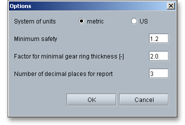
Here you can specify the nominal operating torque. Click the ‘Calculator’ symbol next to the input field to use the dimensioning function and to get a suggestion for an appropriate input value. If you click on the dimensioning button, you get a suggestion for an appropriate input value. The calculation of the value is carried out so that the given minimum safety is fulfilled. The default value for the minimum safety is set to ‘1.2’. Clicking the button ‘Options’ allows you to change this value.

In order to calculate the maximum surface pressure, the share factor is taken into account. Due to manufacturing errors, the surface pressure is unevenly distributed among the teeth (over the circumference) and along the width. The share factor \(k_{\varphi \beta }\) is intended to account these influences. The factor is dependent upon the accuracy of the connection and flank wear.

The following table recommends values for the share factor according to Niemann. Click the ‘Lock’ button to enable the input field and to add your own value.
| Form Closed Connection | Interference Fits | Involute Spline with Involute Flanks
| ||||||
| Number | Tolerance Sequence according to DIN 5480
| |||||||
| 1 | 2 | H5/IT4 | H7/IT7 | H8/IT8 | H9/IT9 | H11/IT11 | Max. Value |
|
| \(k_{\varphi \beta }\) for \(T_{eq}\) | 1 | 1,3 | 1,1 | 1,3 | 1,5 | 2 | 4 |
|
| \(k_{\varphi \beta }\) for \(T_{max}\) | 1 | 1,1 | 1 | 1,1 | 1,3 | 1,7 | 3 | z/2 |
Load peaks occur when the torque clearly exceeds the equivalent torque \(T_{eq}\). Special cases may occur due to starting impacts, short-circuit torques, emergency breaking torques, abrupt blockings etc. The frequency \(N_{L}\) of the load peaks has to be estimated during the entire operating time.

The number of load peaks can be selected from the listbox. It is also possible to define an own number of load peaks. Select the entry ‘user defined input’. The input field next to the listbox is enabled and you can add your value.
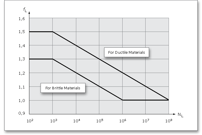
For a single load peak, depending on the ductility of the material, the 1.3 to 1.5 times the permanent surface
pressure is allowed. The load peak frequency factor \(f_{L}\) evaluates the influence of the load peaks on the maximum
surface pressure. If you click on the ‘Calculator’ button next to the input field, you will get a suggestion for an
appropriate value. The calculation of the value is carried out so that the given minimum safety of ‘1.2’ is
fulfilled.
Please note: A maximum load peak torque is greater than the equivalent torque \(T_{eq}\) that results from the
multiplication of the nominal torque and application factor.
The progress of \(f_{L}\) for ductile and brittle materials over the frequency is shown in figure 5 according to DIN 6892.
Click the listbox to define the kind of load for your calculation. Decide between:

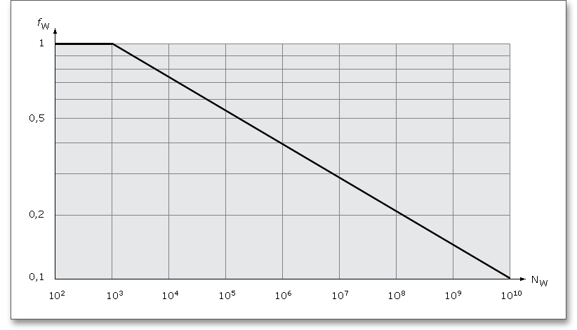
In case you have an alternating torque, then the load direction change is automatically activated and the load direction changing factor \(f_{W}\) is determined. You will find the entry ‘user defined input’ in the listbox. If you select this option, the input field will be enabled, so that you can enter your own input value for the load direction change.

The load direction changing factor \(f_{W}\) is dependent upon the frequency \(N_{W}\) of changes of load direction. The following figure according to DIN 6892 illustrates the relationship between \(f_{W}\) and \(N_{W}\) for alternating torques.
Select an appropriate material for shaft and hub directly from the listbox. Clicking the button ‘Material’ opens the material database.

The material database provides some detailed information on the several kinds of material. If the listbox is active, the two arrow keys ‘Up’ and ‘Down’ of your keyboard allows you to search through the database, so you can compare the different values with each other.
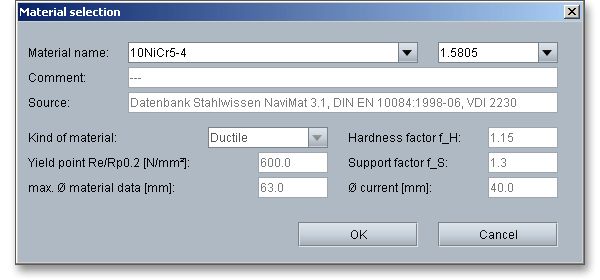
In case there is no material that will fulfill the design requirements, then simply define your individual material. Select the option ‘user defined input’ and all inputs and options are activated and you can specify your individual material very easily. Your inputs will be saved to the calculation file. Please be advised that changing the material will delete your defined inputs and you have to enter the inputs again.
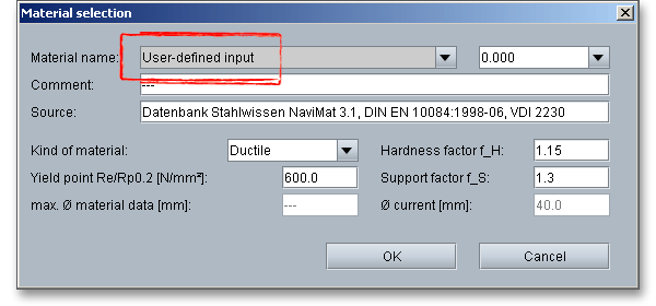
Using the support factor \(f_{S}\), a supporting effect can be considered that occurs for compressive stress components.
From experience, the supporting effect for hubs is larger due to the higher stressed material volume than for
shafts and parallel keys.
The hardness influence factor \(f_{H}\) is determined from the ratio of surface strength to core strength for
case-hardened components. By the hardness influence factor, an increasing of the permissible surface pressure
is considered.
Please note: In case you select ‘User-defined input’ from the material selection, you can define an individual
support factor \(f_{S}\).
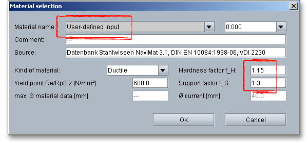
The following table provides values for the support and hardness factor according to DIN 6892.
| Support and Hardness Influence Factors for Different Materials According to DIN 68924
| |||
| Part | Material | \(f_{S}\) | \(f_{H}\) |
| Shaft | Structural steel according DIN EN 10025 | 1,3 - 1,7 | 1,0 |
| Heat-treated steel according DIN EN 10083-1 and DIN EN 10083-2 | 1,3 - 1,7 | 1,0 | |
| Case-hardened steel according DIN 17210 | 1,3 - 1,7 | 1,15 | |
| Gray cast iron with lamellar graphite according DIN EN 1563 | 1,3 - 1,7 | 1,0 | |
| Steel casting according DIN 1681 | 1,3 - 1,7 | 1,0 | |
| Gray cast iron with lamellar graphite according DIN EN 1561 | 1,1 - 1,4 | - | |
| Hub | Structural steel according DIN EN 10025 | 1,5 | 1,0 |
| Heat-treated steel according DIN EN 10083-1 und DIN EN 10083-2 | 1,5 | 1,0 | |
| Case-hardened steel according DIN 17210 | 1,5 | 1,15 | |
| Gray cast iron with spheroidal graphite according DIN EN 1563 | 1,5 | 1,0 | |
| Steel casting according DIN 1681 | 1,5 | 1,0 | |
| Gray cast iron with lamellar graphite according DIN EN 1561 | 2,0 | - | |
| 4 from: DIN 6892:2012-08, p. 25, appx. B, table B.1. Support and Hardness Influence
Factors for Different Materials
| |||
The effective surface pressure between parallel key and shaft or hub keyway wall must not exceed the
permissible value. The permissible values result from the material strength - for ductile materials from the yield
point (\(R_{p0,2}\) and/or \(R_{e}\)) and for brittle materials from the tensile strength \(R_{m}\). The calculation can be run by using less
common metallic materials.
A checkbox field allows you to check or uncheck the stepped hub. If you check the option, you can define the outer diameter of the hub \(D_{2}\), the small outer diameter of the hub \(D_{1}\), the width \(c\) as well as the axial distance \(a_{0}\). The outer diameter of the hub \(D_{2}\) is disabled in the main mask ‘Geometry’.

Based on these input values, the load distribution factor according to DIN 6892 is determined for a different load input and output.
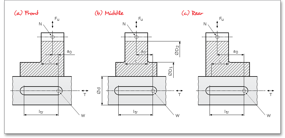
For a stepped hub, it means (see above figure):
| \(D_{1}\) | Small outer diameter of stepped hub |
| \(D_{2}\) | Large outer diameter of stepped hub |
| \(a_{0}\) | Distance between the axial cutting planes through N and W |
| \(c\) | Width of the hub with \(D_{2}\) within the carrying part of the parallel key, i.e., \(c \leq l_{tr}\) |
| Point \(N\): | Idealized point of load input and load output in hub |
| Point \(W\): | Indicates the begin of load input and load output between shaft and parallel key |
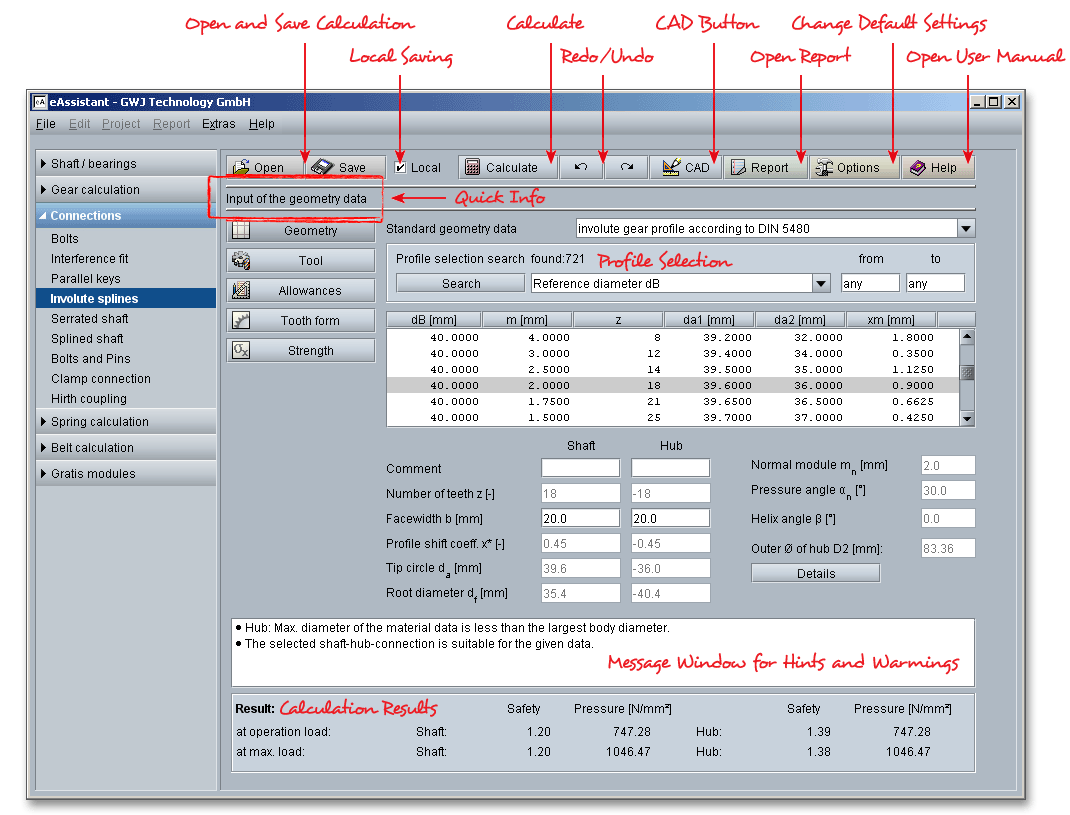
The calculation module provides a message window. This message window displays detailed information, helpful hints or warnings about problems. One of the main benefits of the program is that the software provides suggestions for correcting errors during the data input. If you check the message window carefully for any errors or warnings and follow the hints, you are able to find a solution to quickly resolve calculation problems.

The quick info tooltip provides additional information about all input fields and buttons. Move the mouse pointer over the input field or button, then you will get the additional information. This information will be displayed in the quick info line.

All results will be calculated during every input and will be displayed in the result panel. A recalculation occurs after every data input. Any changes that are made to the user interface take effect immediately. In case a minimum safety is not fulfilled, the result will be marked red. Press the Enter key or move to the next input field to complete the input. Alternatively, use the Tab key to jump from field to field or click the ‘Calculate’ button after every input. Your entries will be also confirmed and the calculation results will displayed automatically.

After the completion of your calculation, you can create a calculation report. Click on the ‘Report’ button.

The calculation report contains a table of contents. You can navigate through the report via the table of contents that provides links to the input values, results and figures. The report is available in HTML and PDF format. Calculation reports, saved in HTML format, can be opened in a web browser or in Word for Windows.
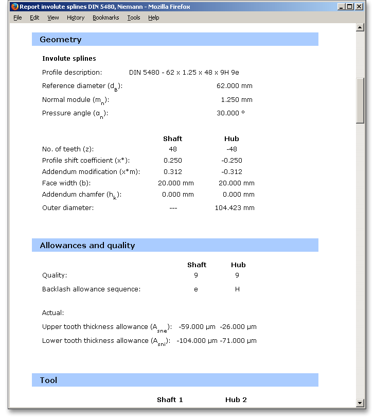
You may also print or save the calculation report:
When the calculation is finished, it is easy to save the calculation. You can save your calculation either to the eAssistant server or to your computer. Click on the button ‘Save’.

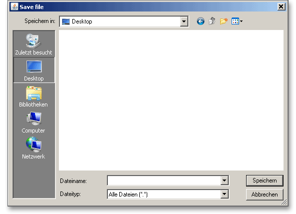
Before you can save the calculation to your computer, you need to activate the checkbox ‘Local’ in the calculation module. A standard Windows dialog for saving files will appear. Now you will be able to save the calculation to your computer.
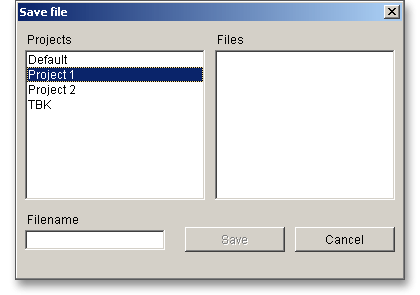
In case you do not activate the option in order to save your files locally, then a new window is opened and you can save the calculation to the eAssistant server. Please enter a name into the input field ‘Filename’ and click on the button ‘Save’.
The ‘Undo’ button allows you to reset your inputs to an older state. The ‘Redo’ button reverses the undo.

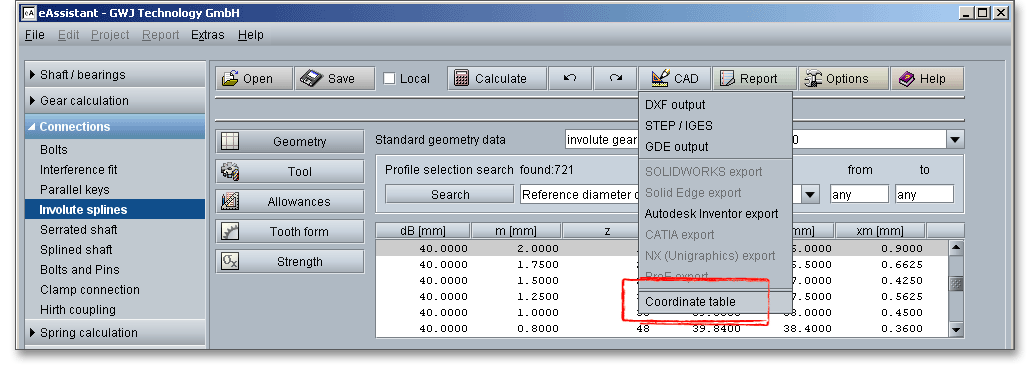
The top menu bar of the eAssistant provides the button ‘CAD’. The eAssistant plugin for various CAD systems (e.g., SOLIDWORKS, Solid Edge, Autodesk Inventor) enables you to combine calculation and design very easily. On the basis of the eAssistant calculation, you can generate the shaft and the hub in a 2D DXF format or create as a 3D part within seconds.

Click on the menu item ‘CAD \(\Rightarrow \) DXF Output’. Now you are able to create the accurate tooth form of any involute gearing in the 2D DXF format. Use the various settings for the DXF output.

For the DXF output the following options are possible:
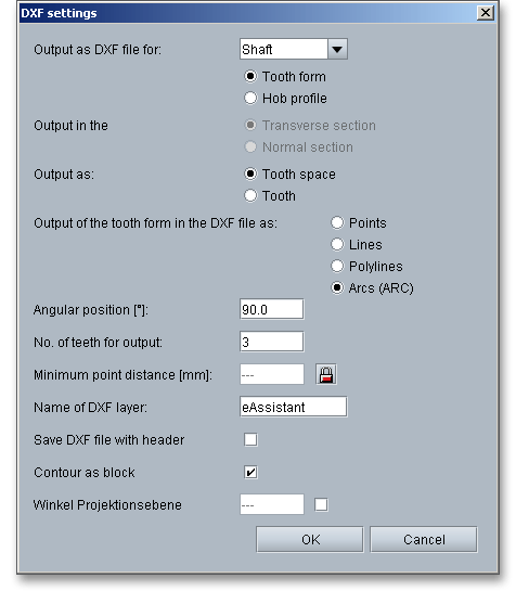
Please note: When you have defined all settings, then click on the button ‘OK’. A standard Windows dialog is
opened to save the file.
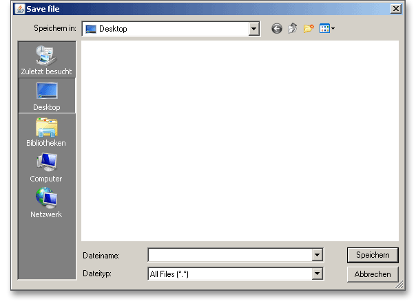
Now you can save the DXF file to your computer. Enter a name for the file and click on the button ‘Save’. It is not
necessary to specify the file extension. The file is identified automatically.
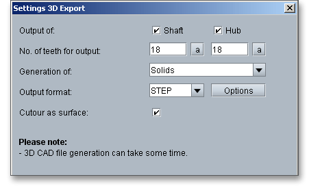
Using this function allows to create the geometry of involute splines as 3D CAD models in STEP or IGES format. STEP as well as IGES are two standardised neutral file formats for CAD models. Almost every 3D CAD system can import STEP files.

The settings menu for the STEP and IGES output has a few different functions and allows to adjust the export options as needed. The geometry can be generated as a solid model with one or all teeth or as a surface model of the tooth space geometry. When exporting to a CAD system, you can also set the level of accuracy to a desired value.
With the integration of the standardised GDE format into the modules for gears and involute splines, eAssistant takes a step closer to a seamless data workflow. GDE stands for Gear Data Exchange. This format, which is defined in VDI/VDE guideline 2610, is already supported by many measuring machine manufacturers. With the GDE format, geometries of cylindrical gears and involute splines can be loaded directly from the software into the measuring machine. It only takes a few clicks to create a measuring program. This avoids transmission errors and allows to work with standard measuring instructions.

The eAssistant plugin for various CAD systems (e.g., SOLIDWORKS, Solid Edge, Autodesk Inventor) enables you to combine calculation and design very easily and fast. Based on your eAssistant calculation, you can generate the shaft and the hub as a 3D part within seconds. A single menu pick in the eAssistant software transfers the eAssistant calculation data to the CAD system. Based on these parameters, the automatic creation of a 3D parametric model starts in the CAD system.

The CAD model stores all features and dimensions as design parameters. The eAssistant calculation is linked
and associated to the part and can be opened at any time throughout the entire design phase.
This is also possible if one part contains different calculations. Click the button ‘CAD’ and select
the CAD plugin. Open the CAD system and start the generation by clicking the integrated button
‘eAssistant’.
Please note: First you need to download and install the right CAD plugin for your CAD system. The
plugin is available on our web site www.eAssistant.eu. After installation, an integrated button called
‘eAssistant’ appears in the CAD system.
With just one click, the design table with all manufacturing details can be placed on the drawing. The
appearance and size of that table is individually configurable. There is no need to manually add all design table
parameters to the drawing. For further information, please visit our web site www.eAssistant.eu or read the
CAD plugin manual.
The gear tooth form geometry of a tooth space can be exported as a coordinate text file in transverse section as well as in normal section.
Click on the button ‘Options’ in the top menu bar of the eAssistant software to change some general settings.

Change the unit system, the minimum safety, the factor for the minimum ring gear thickness. This factor controls the value for the largest possible bore diameter (inner diameter) for external gears and the smallest possible outer diameter for internal gears. The default value \(2.0\) refers to forged gears (see main mask ‘Geometry’), recommendations according to Schlecht (Maschinenelemente 2, 2010): gear ring thickness for extreme lightweight constructions \(< 2 \cdot m\), cast constructions \(5 ... 8 \cdot m\), for welded constructions \(3 ... 5 \cdot m\). or the number of decimal places for the calculation report. To make a permanent change to the calculation module, you can save your settings to a template file.
