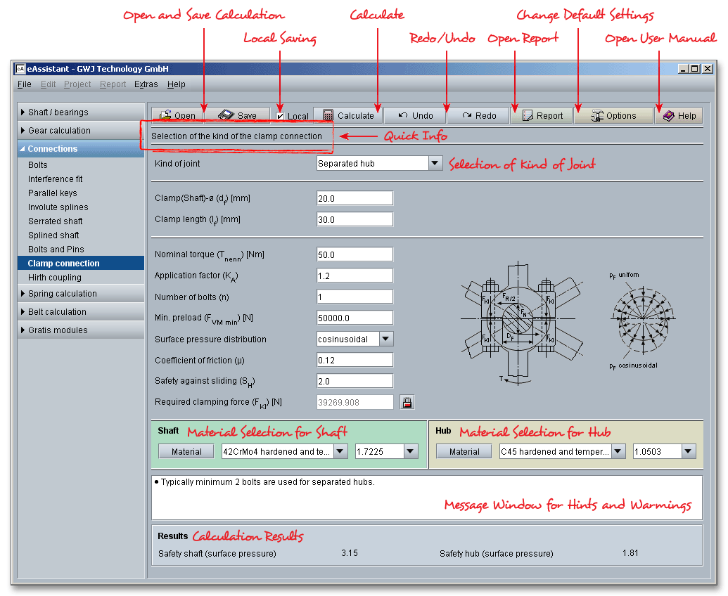
Please login with your user name and your password. To start the calculation module for clamp connections, please click the menu item ‘Connections’ on the left side and then select ‘Clamp connection’.

A clamp connection is a frictional connection, mostly a detachable connection between two components. The frictional connection is produced by means of pretensioned bolts or springs. Clamp connections are suitable to transfer small or medium torques (little fluctuation) and are mainly used in precision engineering. For larger torques, a clamp connection is additonally secured using parallel keys or tangential keys. The eAssistant module for clamp connections allows the design and calculation of both separated hubs and split hubs. The calculation is based on Roloff/Matek Maschinenelemente (17th revised edition 2005).
Advantages of Clamp Connections:
Disadvantages of Clamp Connections:
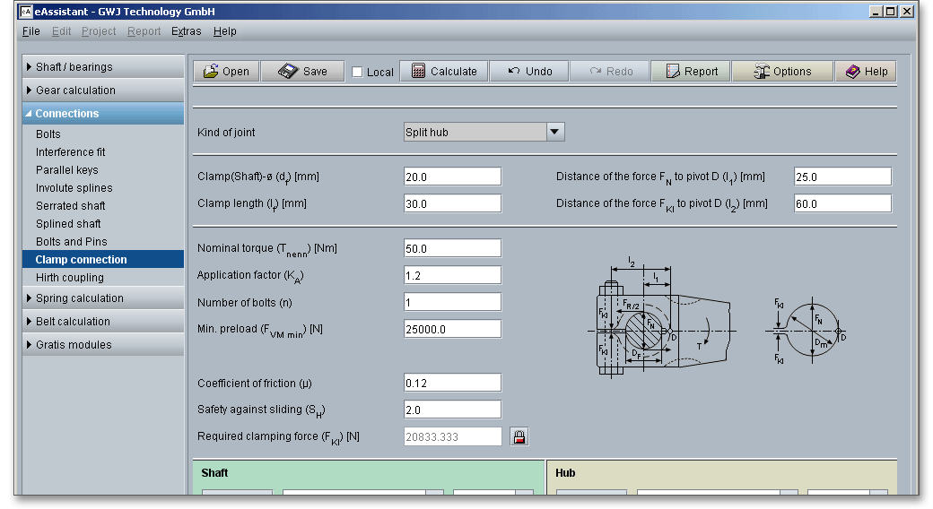
This is where you select the type of the connection. The calculation module considers two designs: the separated hub and the split hub. In order to select one of the two designs, please click the listbox and choose either separated or split hub.

In the case of separated hubs, the pressure is distributed uniformly over the entire joint. A differentiation is made between uniform and cosine form surface pressure and linear contact. If there are no high requirements regarding the transmission capability, then the separated hub design can be used. Materials suitable for the separated hub are steel, cast steel, malleable cast iron or cast iron.

Click the listbox to specify the distribution of the surface pressure. There are three possibilities for you here:
cosine form, uniform and linear distribution.
The split hub design is used mainly in precision engineering. The manufacturing is pretty easy and not expensive. For split hubs, it is recommended to use a narrow fit (e.g., H7/g6) because the hub is subjected to bending. Steel is a suitable material for split hubs.
The following table gives some values for the application factor \(K_{A}\) for clamp connections.
| Application Factors \(K_{A}\) According to DIN 3990-1: 1987-121
| ||||
| Working Characteristics | Working Characteristics of the Driven Machine | |||
| of the Driving Machine | Uniform | Light shocks | Moderate shocks | Heavy shocks |
| Uniform | 1.0 | 1.25 | 1.5 | 1.75 |
| Light shocks | 1.1 | 1.35 | 1.6 | 1.85 |
| Moderate shocks | 1.25 | 1.5 | 1.75 | 2.0 |
| Heavy shocks | 1.5 | 1.75 | 2.0 | 2.25 or higher |
| 1 from: DIN 3990 Part 1, December 1987, p. 55, table: A1
| ||||
Working Characteristics of the Driving Machine
Working Characteristics of the Driven Machines
With the pressure \(p_{f}\), clamp connections can be considered as shrink fits. The following table provides some approximate values for the coefficients of friction for shrink fits according to DIN 7190. The values are on the safe side and can be used for sliding in circumferential and longitudinal direction. For the safety against sliding, a value of \(S_{H} \geq 1,5\) is recommended.
| Coefficients of Adhesion for Shrink Fits in
| |
| Longitudinal and Circumferential Direction During Sliding According to DIN 7190 | |
| Mating of Material, Lubrication, Joining | Coefficients of Adhesion \(\nu _{R}, \nu _{rl}, \nu _{u}\) |
| Steel/Steel pair |
|
| Pressurized oil assembly normally joined with mineral oil | 0.12 |
| Pressurized oil assembly with degreased surfaces joined with glycerine | 0.18 |
| Shrink fit normally after heating the outer part up to \(300^{\circ }\)C in an electric kiln | 0.14 |
| Shrink fit with degreased surfaces after heating up to \(300^{\circ }\)C in an electric kiln | 0.20 |
| Steel/Cast iron pair |
|
| Pressurized oil assembly normally joined with mineral oil | 0.10 |
| Pressurized oil assembly with degreased surfaces | 0.16 |
| Steel/MgAl pair, dry | 0.10 to 0.25 |
| Steel/CuZn pair, dry | 0.17 to 0.25 |
With the definition of geometry, nominal torque, number of bolts as well as coefficients of friction, the required clamping force will be determined. There is the possibility to enable the input field of the clamping force by using the ‘Lock’ button. Clicking the ‘Lock’ button allows you to modify the clamping force very easily. Let the ‘Lock’ button open. If you close the button, then the input field is disabled and the value is determined again according to Roloff/Matek.

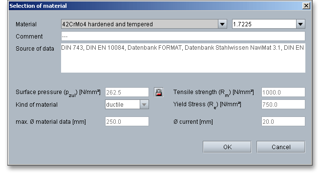
Select an appropriate material for the shaft and hub directly from the listbox or click on the button ‘Material’ to open the material database.

The material database provides some detailed information on the several kinds of material (e.g., surface pressure, tensile strength, yield stress). If the listbox is active, the two arrow keys ‘Up’ and ‘Down’ of your keyboard allows you to search through the database, so you can compare the different values with each other.
In case there is no material that will fulfill the design requirements, then simply define your individual material. You will find the entry ‘User defined’ in the listbox. If you select this option, the input fields will be enabled, so that you can enter your own input values or add a comment. You can enter the surface pressure, tensile strength and yield stress.
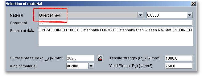
The permissible surface pressure is automatically determined from the yield stress depending
on the kind of material. It is possible to modify the surface pressure. Click the ‘Lock’ button and
enter a value into the input field. In order to confirm your inputs, click the button ‘OK’. Please be
advised that changing the material will delete your defined inputs and you have to enter the inputs
again.
The calculation module provides a message window. This message window displays detailed information, helpful hints or warnings about problems. One of the main benefits of the program is that the software provides suggestions for correcting errors during the data input. If you check the message window carefully for any errors or warnings and follow the hints, you are able to find a solution to quickly resolve calculation problems.

The quick info tooltip provides additional information about all input fields and buttons. Move the mouse pointer over the input field or button, then you will get the additional information. This information will be displayed in the quick info line.

All important calculation results (e.g., safeties of shaft and hub) will be calculated during every input and will be displayed in the result panel. A recalculation occurs after every data input. Any changes that are made to the user interface take effect immediately.

In case a minimum safety is not fulfilled, the result will be marked red. Press the Enter key or move to the next
input field to complete the input. Alternatively, use the Tab key to jump from field to field or click the ‘Calculate’
button after every input. Your entries will be also confirmed and the calculation results will displayed
automatically.
After the completion of your calculation, you can create a calculation report. Click on the ‘Report’ button.

The calculation report contains a table of contents. You can navigate through the report via the table of contents that provides links to the input values, results and figures.
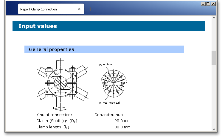
The report is available in HTML and PDF format. Calculation reports, saved in HTML format, can be opened in a web browser or in Word for Windows. You may also print or save the calculation report:
When the calculation is finished, it is easy to save the calculation. You can save your calculation either to the eAssistant server or to your computer. Click on the button ‘Save’.

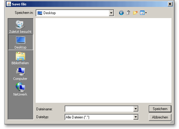
Before you can save the calculation to your computer, you need to activate the checkbox ‘Local’ in the calculation module. A standard Windows dialog for saving files will appear. Now you will be able to save the calculation to your computer.
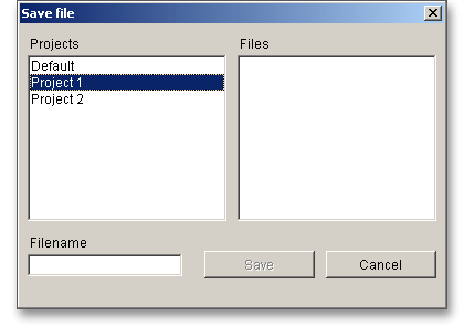
In case you do not activate the option in order to save your files locally, then a new window is opened and you can save the calculation to the eAssistant server. Please enter a name into the input field ‘Filename’ and click on the button ‘Save’.
The ‘Undo’ button allows you to reset your inputs to an older state. The ‘Redo’ button reverses the undo.

Click on the button ‘Options’ in the top menu bar of the eAssistant software to change some settings, for example the unit system, the minumum safeties of shaft and hub or the number of decimal places for the report.

You can also modify the surface pressure calculation factor \(p_{zul}\). To calculate the permissible surface pressure \(p_{zul}\) for ductile materials, this factor is multiplied by the yield stress \(R_{e}\). To calculate the permissible surface pressure for brittle materials, this factor is multiplied by the tensile stress \(R_{m}\).