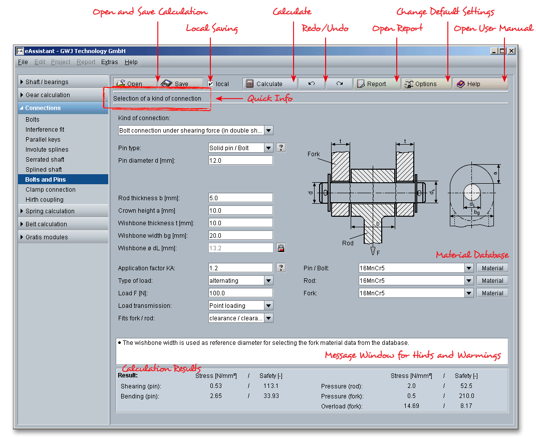
Please login with your username and your password. To start the calculation module for bolts and pins, please click the menu item ‘Connections’ on the left side and then select ‘Bolts and pins’.

Components can be connected together with bolt and pins. Pins are used when it is necessary to connect, mount, fix and seal components. Bolts are used for the transmission of shear forces and combine two or more parts, but mostly a movable part remains. All calculations are based on accepted technical literature books (e.g., Niemann or Decker).
The functions of pins:
The functions of bolts:
Using this calculation module, the listbox allows to select the following cases of application:

Select a certain kind of connection, then the relevant input fields that are required for the determination of the
connection are displayed. You will get a graphical representation for for every kind of connection.
If a shaft is connected with a hub by a longitudinally inserted round key, then a longitudinal pin under torque is developed.

Due to the force \(F\) acting in the pin, a bending moment as well as a shearing force occur which result in a combined bending and shearing load.

If the outer part and the inner part are connected with a pin having the diameter \(d\), then a cross pin under torque is developed.

The bolt is subjected to bending, shear and surface pressure. The bending is a decisive factor for not sliding surfaces, for sliding surfaces the surface pressure is decisive.

Pins differ in terms of their form. The selection of a pin type depends on the different requirements (e.g., requirements for accuracy, manufacturing costs, tightness, disassembly as well as required shear strength). Please select one of the following pin types using the listbox:

Please note: Click on the ‘Question mark’ button next to the listbox. Then you will get an overview of the
different pin and bolt types.
A bolt is used to fasten two or more members together, a pivoting movement is allowed between the parts. A clearance fit requires a safety device against falling out. For split pins, bolts must have transverse holes, grooves are necessary for retaining rings and washers. For reasons of cost, pins without head are preferred. The following types of bolts can be distinguished:
|
| A Pins without head |
Pins without head are used as a hinge pin for connecting rods. Pins with head are used as fixed bearing and
axle bolts (e.g., for rope pulleys).
Grooved pins provide an excellent holding power and their solid construction makes them stronger than spring pins. The fastener is a pin with three longitudinal grooves and is designed to deform when forced into regular drilled holes. A straight drilling hole suffices using an ordinary twist drill. A grooved pin with gorge is ideal for fitting springs or sliding sealing washers. The majority of grooved pins are made of steel or austenitic stainless steel. In order to prevent the risk of scuffing, the strength of the pins has to be larger than the strength of the components.
High-strength pin material should be used for hardened steel and cast iron.
|
| A Grooved pin with gorge |
Along with hexagon screws, dowel pins join two pieces together. Dowel pins are made of rolled spring band steel, steel, austenitic stainless steel and martensitic stainless steel.
|
| A Dowel pin |
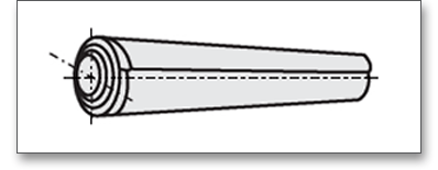
Coiled spring pins are press fit fasteners. For low accuracy requirements, coiled spring pins serve as a locking device or transmit transverse forces. Coiled spring pins are made of cold steel strip rolled into a spiral spring.
It is recommended that the pins should consist of a harder material than the components to avoid deformation when the pin is inserted or removed. Due to the difference in hardness, seizing in the hole can be avoided. In order to prevent the risk of scuffing and excessive wear, it is preferable to use a bolt material which is harder and stronger than the material of the components

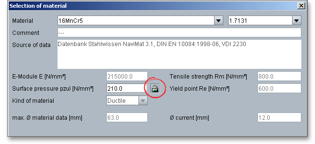
Standard bolts are made of free cutting steel. Highly-loaded hinge pins are made of case-hardened, quenched and tempered steel and are heat-treated and ground. Select an appropriate material directly from the listbox or click on the button ‘Material’ to open the material database. The material database provides some detailed information on the several kinds of material (e.g., elastic modulus, surface pressure, tensile strength). Click on the ‘Lock’ button next to the field ‘Surface pressure’ to enable the input field and enter your own value based on your experience.
In case there is no material that will fulfill the design requirements, then simply define your individual material.
You will find the entry ‘User-defined’ in the listbox. If you select this option, the input fields will be enabled, so
that you can enter your own input values or add a comment. In order to confirm your inputs, click the button ‘OK’.
Please be advised that changing the material will delete your defined inputs and you have to enter the inputs
again.
Here are some reference values for the application factors \(K_{A}\) for welded and rivet joints, bolts and pins.
| Reference Values for the Application Factor \(K_{A}\)
| |||
| for Welded and Rivet Joints, Bolts and Pins1 | |||
| Operating Mode | Kind of Machine and Components (Examples) | Kind of shocks | \(K_{A}\) |
| Uniform rotating movements | Electric machines, grinding machines, steam and water turbines, circulating compressor | Light | 1.0 ... 1.1 |
| Uniform reciprocating movements | Steam engines, combustion engines, planing and turning machines, piston compressor | Medium | 1.2 ... 1.4 |
| Rotating and reciprocating movements | Molding press, bending and straightening machines, rolling mill drives | Moderate | 1.3 ... 1.5 |
| Striking movements | Screw presses, hydraulic forging presses, mechanical press brake, section shearing machine, reciprocating saws | Heavy | 1.5 ... 2.0 |
| Impact loading | Stone crusher, hammer, cold shear for rolling mills, roll stands, crushing machines | Very heavy | 2.0 ... 3.0 |
| 1 from: Dieter Muhs, Herbert Wittel, Dieter Janasch, Joachim Vossiek: Roloff/Matek
Maschinenelemente: Tabellen, 17th ed. 2005, Vieweg Verlag, p. 42, table 3-5
| |||
|
| Machine (Examples) | |||
| Working | Speed in \(min^{-1}\) | Reference Value | \(K_{A}\) | |
| characteristics | \(\leq {3600}\) | \(\geq {3600}\) | ||
|
| Electric motor (d.c. motor) | Generators for | ||
|
| uniform operation, rare | basic load or | ||
| Uniform | starting, uniform loaded | cont. operation, | Nominal torque | |
| to low | conveyor belt, packing, | grinding machine, | ||
| shocks | machinery, feed drive for | compressor for | 1.0 to 1.1 | |
|
| machine tools, ventilators | air con | ||
|
| Shear, presses, | Max. cutting, pressing, | ||
|
| stamping machines | stamping torque | ||
|
| Vertical gears, | Maximum | ||
|
| running gears | starting torque | ||
|
| Electric motor (a.c. motor) | Generators for | ||
|
| frequent starting, | peak load, | ||
| Light to | main drive for | gear pumps, | Nominal torque | |
| middle | machine tools, | centrifugal and | ||
| shocks | conveyor for unit loads, | radial compressor, | 1.2 to 1.5 | |
|
| rotary pumps | paper machine | ||
|
| Overburden conveyance, | |||
|
| carts for transport and | Static axle load | ||
|
| steel mill operation | |||
|
| Continuous rolling | Maximum | ||
|
| mill stands | rolling torque | ||
|
| Multiple cylinder | |||
|
| Single cylinder reciprocating | piston pumps, | ||
| Moderate | wood working machine | industrial | Nominal torque | |
| shocks | light ball mills | ventilators for | ||
|
| frequent starting | 1.5 to 2 | ||
|
| Max. rolling torque | |||
|
| Billet rolling mill | (current limitation) | ||
|
| Lifting gear | Max. lifting force | ||
|
| Screw press | Max. pressing force | ||
|
| Excavator, heavy ball | Reciprocating | ||
| Heavy shocks | mills, crushers (stone, ore), | machine | Nominal torque | 2 to 3 |
|
| mechanical hammer | 2 or 1 cylinder | ||
| from: Niemann, Winter, Hoehn: Maschinenelemente, Vol.1, 3rd ed. 2001, Springer Verlag, p. 17, fig.
1.11
| ||||
The calculation module provides a message window. This message window displays detailed information, helpful hints or warnings about problems. One of the main benefits of the program is that the software provides suggestions for correcting errors during the data input. If you check the message window carefully for any errors or warnings and follow the hints, you are able to find a solution to quickly resolve calculation problems.

The quick info feature gives you additional information about all input fields and buttons. Move the mouse pointer to an input field or a button, then you will get some additional information. This information will be displayed in the quick info line.

All important calculation results (e.g., pressures, stresses and safeties) will be calculated during every input and will be displayed in the result panel. A recalculation occurs after every data input. Any changes that are made to the user interface take effect immediately. Press the Enter key or move to the next input field to complete the input. Alternatively, use the Tab key to jump from field to field or click the ‘Calculate’ button after every input. Your entries will be also confirmed and the calculation results will displayed automatically. If the result exceeds the minimum safety, the result will be marked red.

After the completion of your calculation you can create a calculation report. Click on the ‘Report’ button.

You can navigate through the report via the table of contents that provides links to the input values, results and figures. This calculation report contains all input data, the calculation method as well as all detailed results. The report is available in HTML and PDF format. Calculation reports, saved in HTML format, can be opened in a web browser or in Word for Windows.
You may also print or save the calculation report:
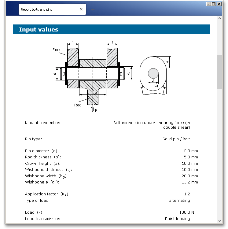
When the calculation is finished, it is easy to save the calculation. You can save your calculation either to the eAssistant server or to your computer. Click on the button ‘Save’.

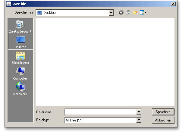
Before you can save the calculation to your computer, you need to activate the checkbox ‘Local’ in the calculation module. A standard Windows dialog for saving files will appear. Now you will be able to save the calculation to your computer.
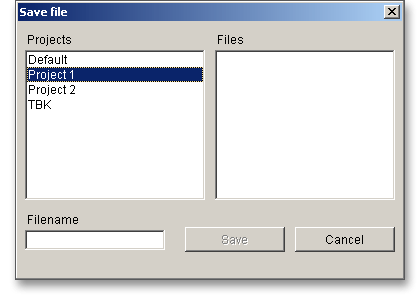
In case you do not activate the option in order to save your files locally, then a new window is opened and you can save the calculation to the eAssistant server. Please enter a name into the input field ‘Filename’ and click on the button ‘Save’.
The button ‘Undo’ allows you to reset your input to an older state. The button ‘Redo’ reverses the undo.

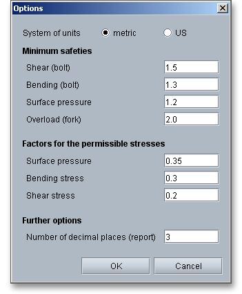
Click the button ‘Options’ in order to change the default settings.

Here you can specify the unit system, the minimum safeties for shear, bending, surface pressure and overload. Permissible stresses for surface pressure, bending stress and shear stress can be also defined.
