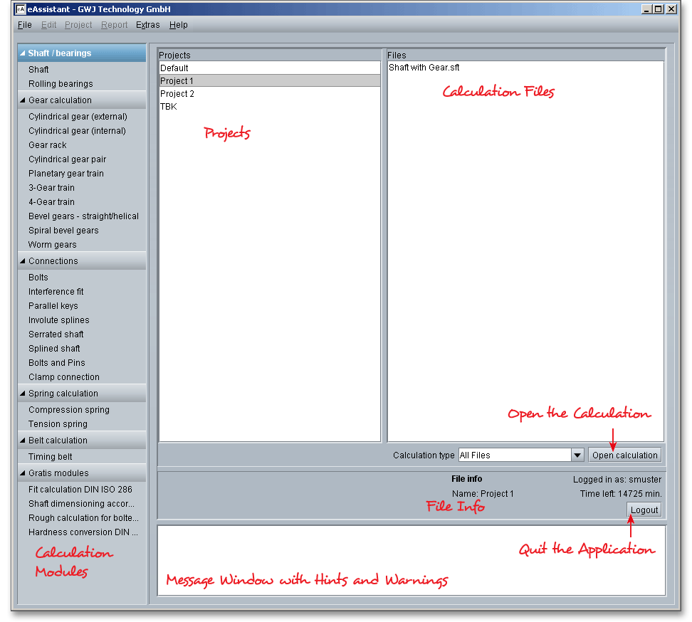
As soon as you have successfully signed in with your username and password, you are presented with the project management screen where you can start all calculation modules. With the project manamgement tool it becomes easy to manage all your projects and calculation files. The project management helps you to open, save, delete, copy or rename projects or calculation files. You can change your personal data or your password here if necessary.

Here you can manage your projects. You can create a new project, you can copy, rename, or delete projects.
The window ‘Files’ lists the content of the selected project.
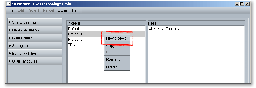
Click in the ‘Projects’ window and click the right mouse button. Select the menu item ‘New project’ from the context menu.
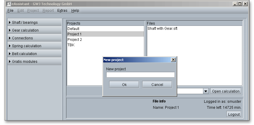
A new input window is opened. Enter a name into the input field and click the button ‘Ok’.
The input window is closed. Now your ‘New project’ is created in the list window ‘Projects’.

Select the project you would like to copy and click the right mouse button. Select the menu item ‘Copy’ from the context menu.
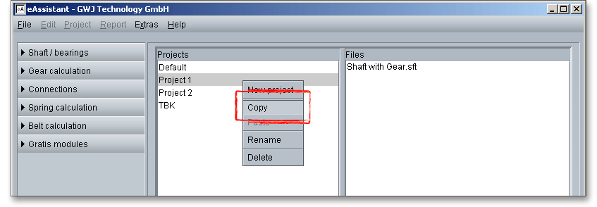
Click in the window ‘Projects’ and click the right mouse button. Select the menu item ‘Paste’ from the context menu.
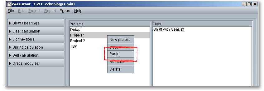
The copied project has got still the title ‘Copy’. You can change the name of that project later. If you copy a project, the content (files) of this project will copied too.
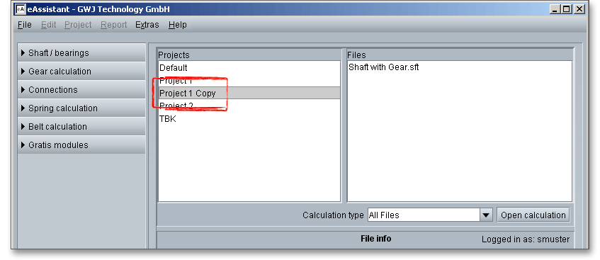
Select the project you would like to rename and click the right mouse button. Select the menu item ‘Rename’ from the context menu.
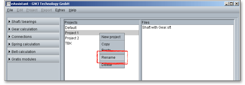
Change the name of the project and confirm with ‘Ok’.
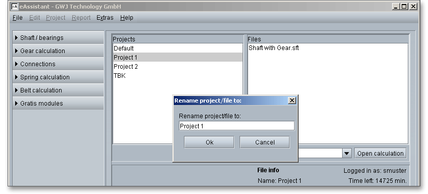
Select the project you would like to delete and then a right-click on this project. Select the menu item ‘Delete’ from the context menu. Answer the prompt with ‘Yes’.
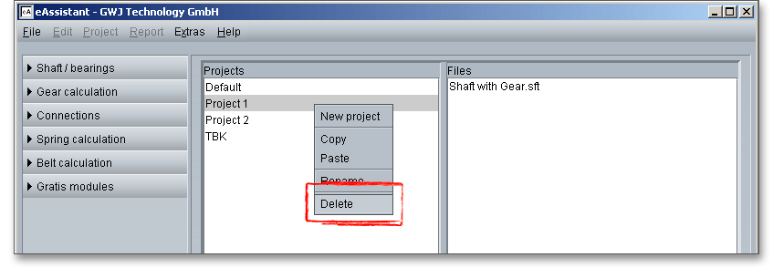
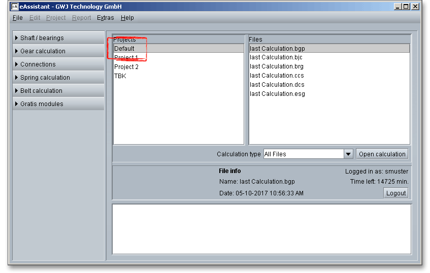
The folder ‘Default’ is a default setting. If you close a calculation module, the current state of the calculation will be saved automatically as a calculation file called ‘last Calculation’ in the project folder ‘Default’. In case you forgot to save your calculation, no data get lost. The calculation modules of the same module will be overwritten when opening and closing the modules. You cannot rename, delete or cut the folder ‘Default’.
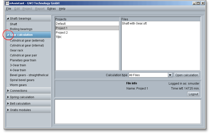
The module tree on the left side shows all calculation modules. Click the arrow to the left to display the modules of each module group. One click starts the module.
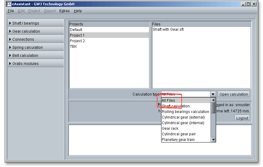
To narrow down the selection to one particular type, choose the calculation type from the list. Click ‘All Files’ to display all calculation files.
To close the calculation module, click the menu item ‘File’, then click ‘Quit calculation’.
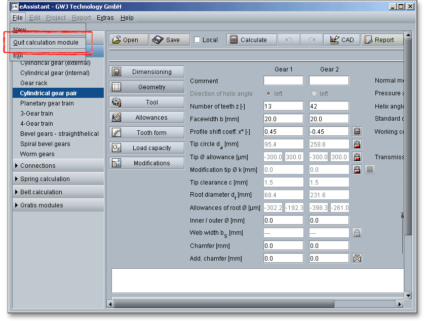
The eAssistant framework provides the flexibility to easily change between the modules. A previously opened module does not need to be reloaded again and is immediately available without waiting. The last calculation will be loaded automatically.
The window ‘Files’ displays all calculation files. By using a filter function, the saved calculation files can be
displayed within a specific module or across modules. Choose a calculation module and see all files which
belong to the respective calculation module.
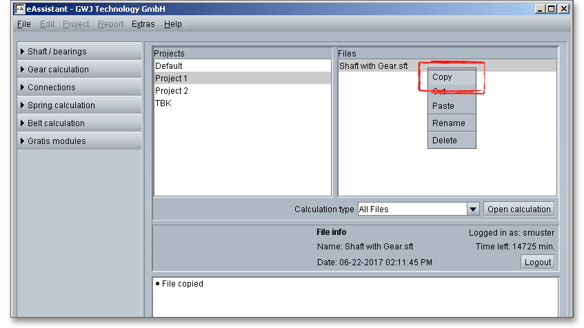
Select the file you would like to copy and click the right mouse button on this file. Select the menu item ‘Copy’ from the context menu.
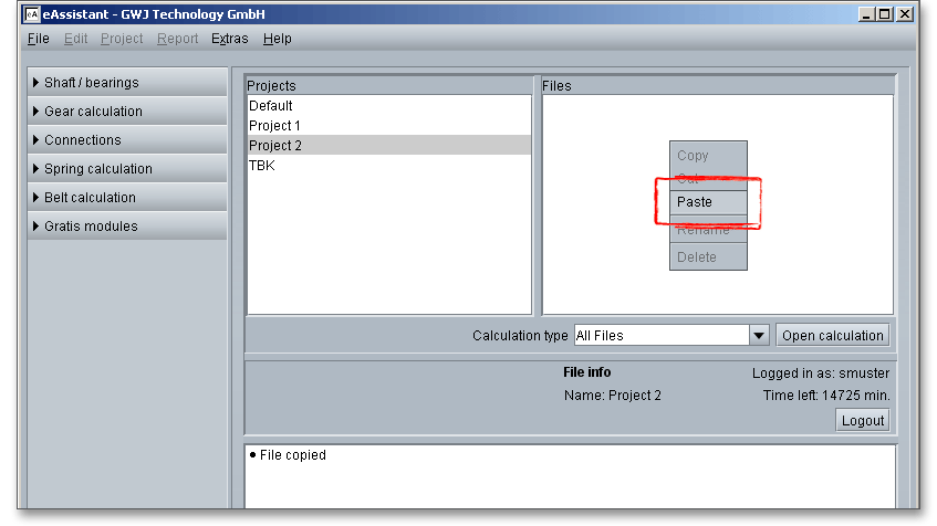
Select the project where you would like to copy the file. Click the right mouse button in the field ‘Files’ and click the menu item ‘Paste’ from the context menu.
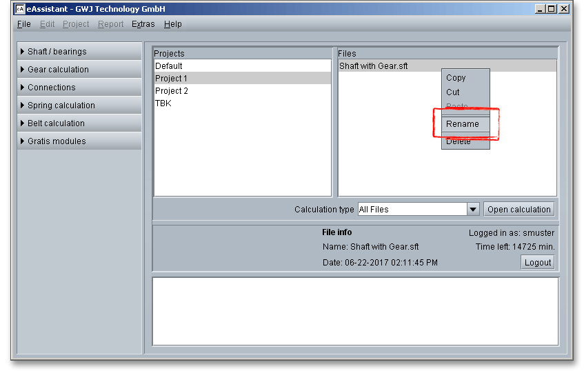
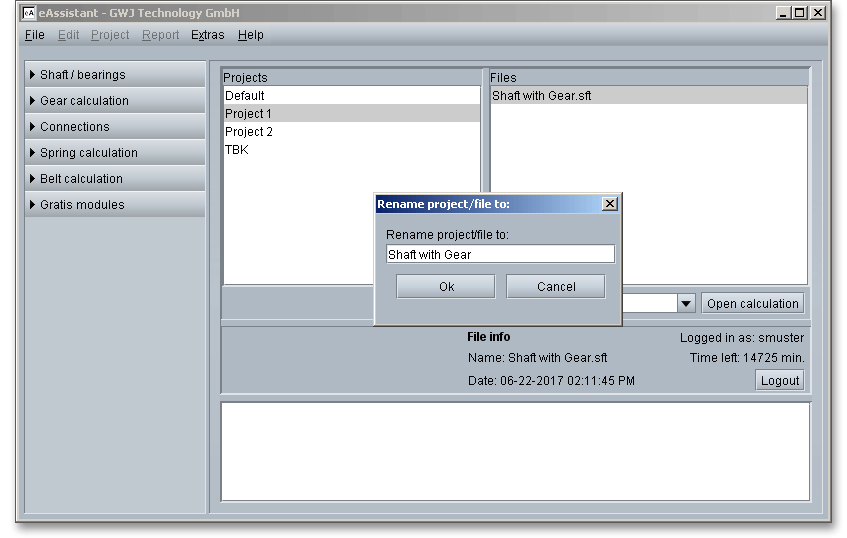
Select the file you want to rename and click the right mouse button on this file. Select the menu item ‘Rename’ from the context menu.
Change the name of the file and click the button ‘Ok’.
Select the file you would like to cut and click the right mouse button on this file. Select the menu item ‘Cut’ from the context menu.

Select the project where you would like to paste the file and click the right mouse button. Select the menu item ‘Paste’ from the context menu.

Select the file you would like to delete and click the right mouse button on this file. Select the menu item ‘Delete’ from the context menu. Answer the prompt with ‘Yes’.

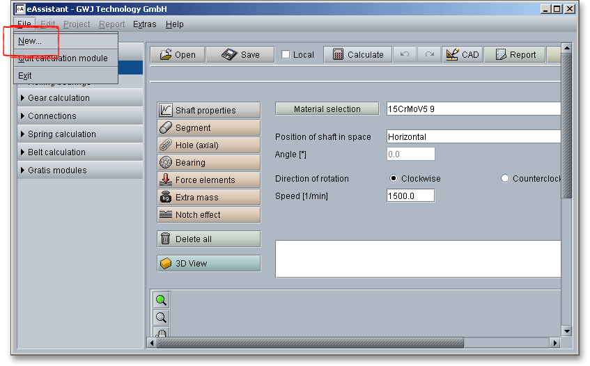
Clicking the menu item ’New’ closes the current calculation and opens the calculation module with the internal default setting for all values. If you have defined your own template file, this template file will then be used when you open the calculation module.
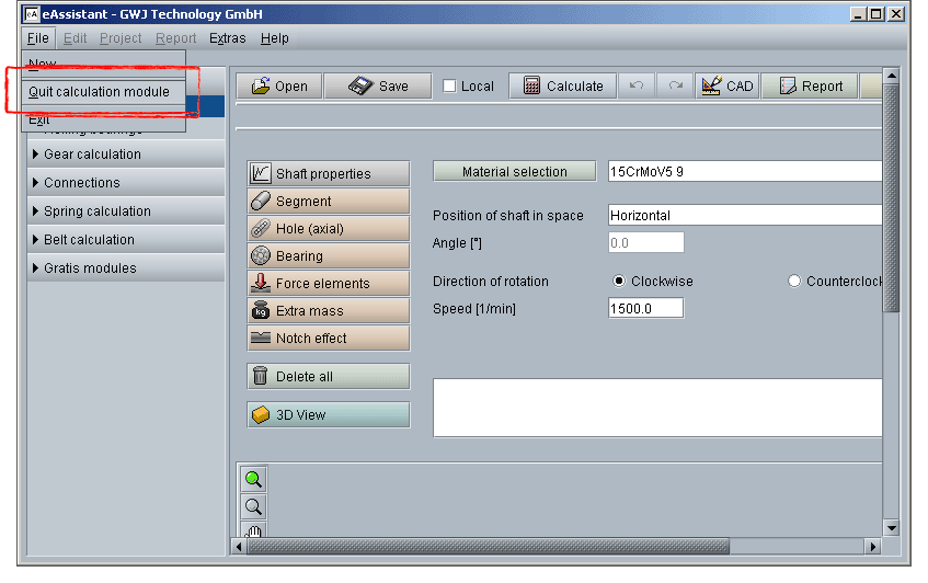
The menu item ‘Quit the Calculation module’, which you´ll find under the ‘File’ menu item, just closes the current calculation module and not the whole program.
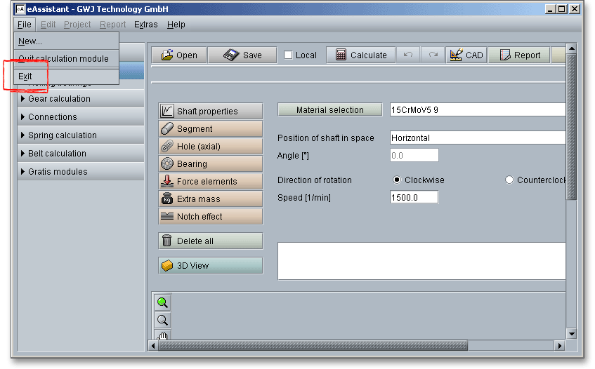
Click the menu item ‘File’ and then the ‘Exit’ button to quit the application. If you close the software without logging out, you will be automatically logged out. But you can immediately return to the eAssistant and re-login with your username and password.
It is easy to switch from one language to another. click the menu item ‘Language’ and select the required language. The software is available in English and German.
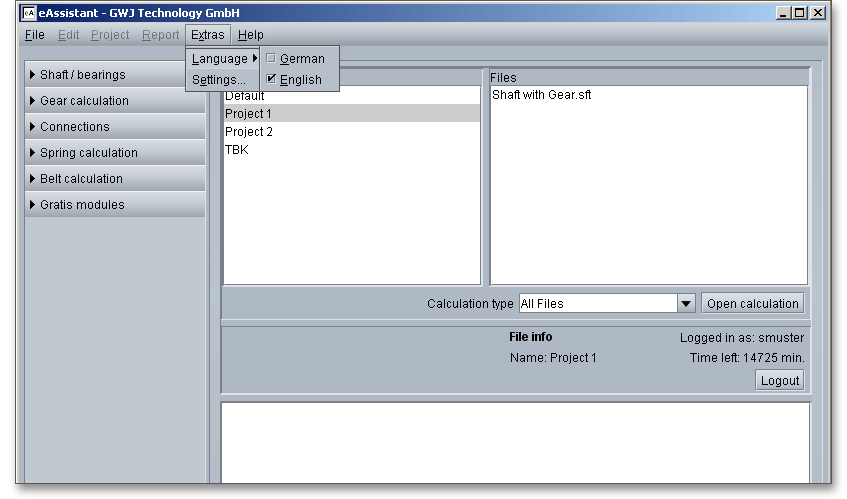
The menu item ‘Settings’ controls the properties of the software as a whole, while the menu item ‘Options’ controls the properties of the individual calculation module. This is where you configure settings like adding a project info, enabling/disabling job data or selecting a short calculation report. If you ever need to change your password, you can do that here.

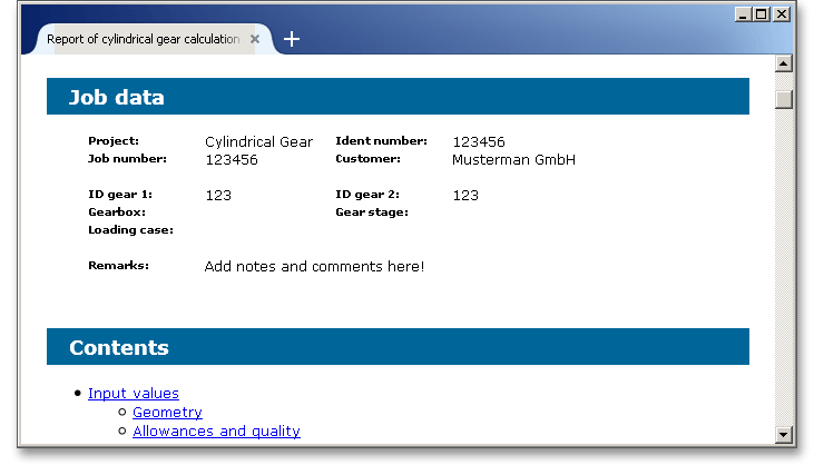
Entering the job data allows to specify an order. In this way you can describe each job in detail and properly document it. In the tree structure on the left side, click ‘General’ and set the checkmark ‘Show a dialog to edit the job data before generating the report’. If you enable this option, the job data is displayed on the screen before the calculation report is opened. That also means that a window is displayed in which you can enter the job data every time a calculation report is generated.
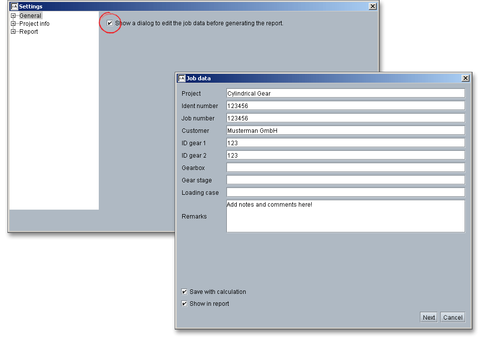
The job data can be saved to the calculation, meaning that you do not have to enter the job data again every time. To do so, please enable the checkbox ‘Save with calculation’. If you save the calculation, the job data is also saved. If you disable the function ‘Show in report’, the job data is not displayed in the calculation report.
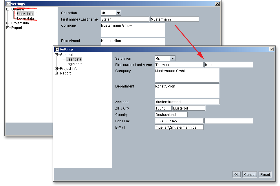
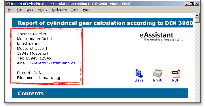
In case several users share the same password and user name, a single user can configurate own user data on the workstation. Later, the data will appear at the top of the generated calculation report and you will be able to see who has created the calculation. The configuration manager is particularly helpful for companies who have multiple parallel accounts. When you start the configuration manager, the module first shows the user data that is saved in the eAssistant ‘User data’. You can customize the user data. Click the button ‘OK‘ to save the modifications.
Open a calculation module from the project management, for example cylindrical gears. You can leave the configuration manager open. Click the button ‘Report’ to generate the calculation report. The modified user data appear in the header section of the calculation report. The general user data will remain in place.
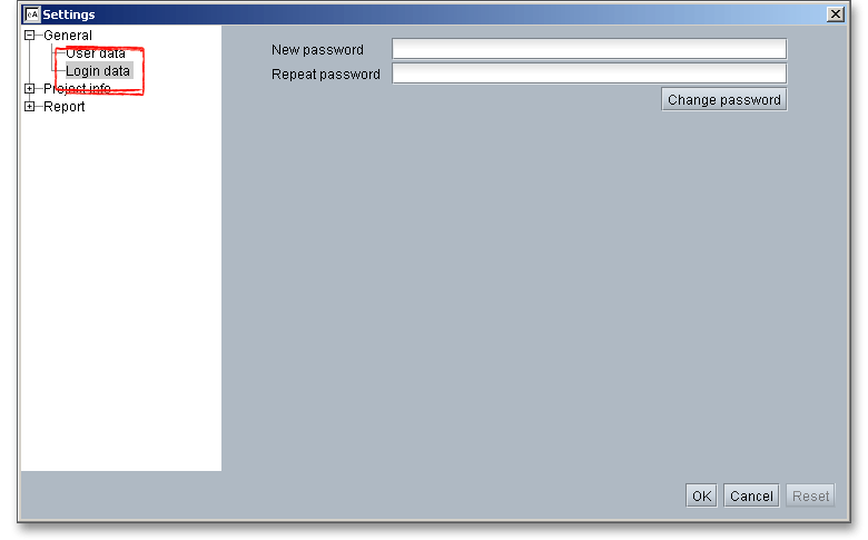
The password can be modified by clicking the menu item ‘Login Data’. Enter the new password into the input field ‘New password’. Confirm the password in the input field ‘Repeat password’ and click the button ‘Change Password’. Confirm with the button ‘OK’.
The program allows you to create a project info. For any project, you can add a describing text, for
example order data or other project-related information (e.g., drive shaft). The text then appears in
the header section on each page of the PDF calculation report. The configuration of the project
info allows you to choose whether to be prompted for confirmation before generating the project
info.
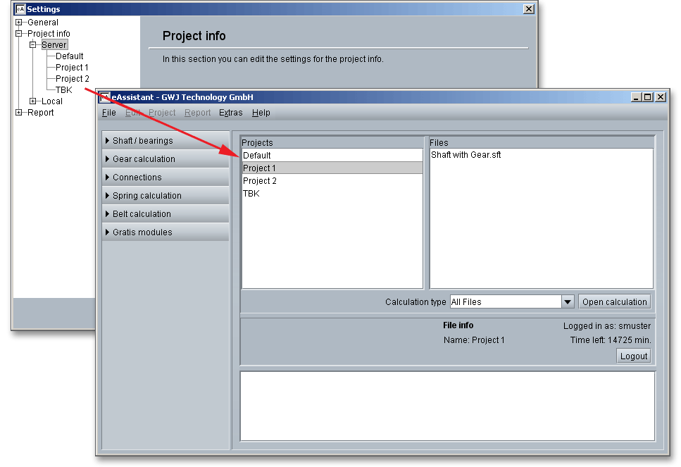
On the left-hand side in the tree view under ‘Project info’ you can find the menu item ‘Server’. If you click this menu item, all existing project files saved in the project management under ‘Projects’ are listed.
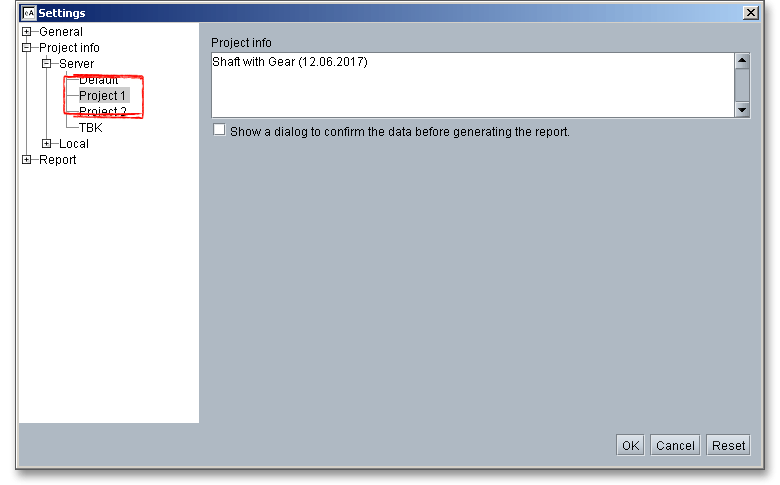
Select a project, for example ‘Project 1’. The text field ‘Project info’ lets you add some text. This text will appear in the header section of the calculation report. Click the button ‘Save project info’ in order to save your text. The added text then applies to all calculation files that belong to this project.
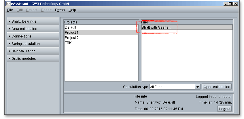
Select the project ‘Project 1’ from the project management and open the calculation ‘Shaft with Gear’ either by double-clicking the file or click the button ‘Open Calculation’.
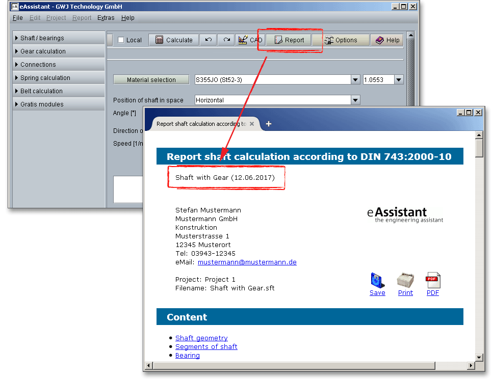
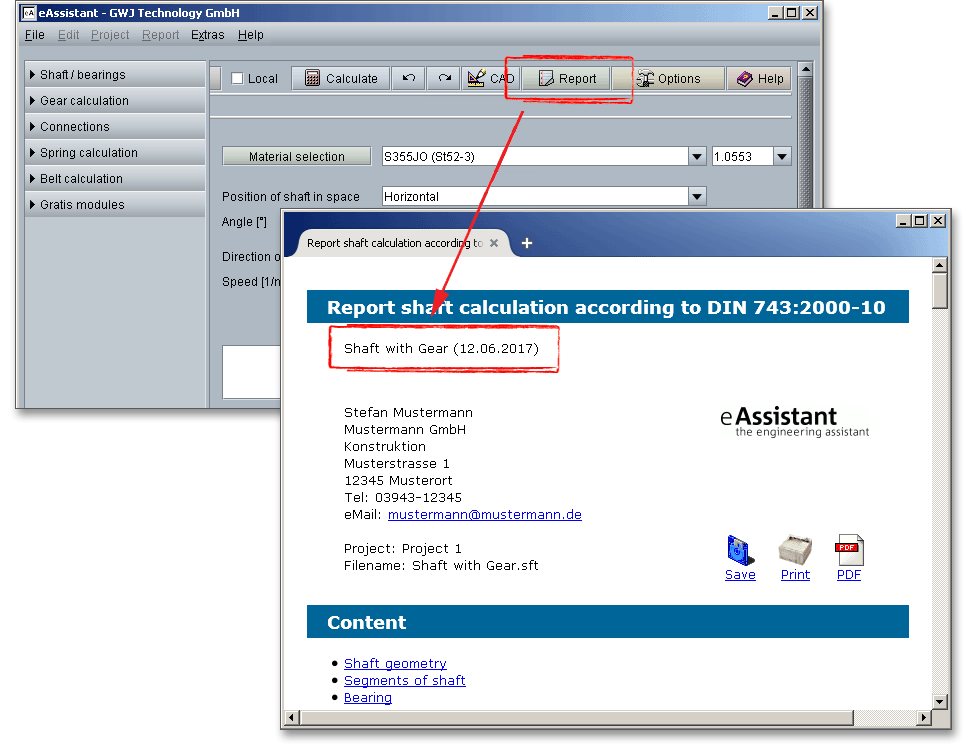
In order to generate the calculation report, click the button ‘Report’ in the calculation module. You can see the newly added text in the upper left corner. If you open the PDF calculation report, then the text will appear at the top of every page in your calculation report.
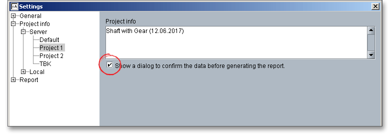
If you check the checkbox ‘Show a dialog to confirm...’, you receive a dialog each time before the generation of the calculation report starts. You can then decide whether to use the added project info or not. If this checkbox is clear, the calculation report is automatically generated and no prompt is displayed.
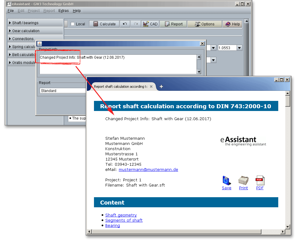
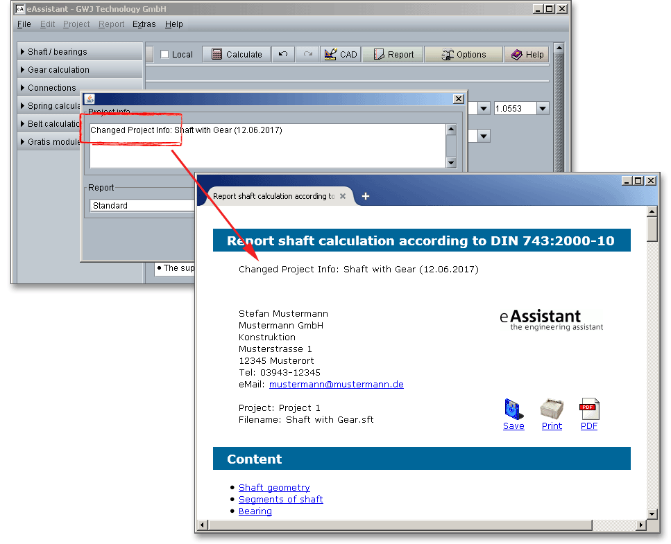
If you choose to place a check mark here, a message window will be opened each time before the generation of the calculation report begins. In this window you can check the project info again and decide if the text contains the information you want. If not, you can overwrite and quickly replace the text. Confirm with the ‘OK’ button and the calculation report including the new project info will be created. But the saved project info in the configuration manager cannot be overwritten and remains unchanged.
On the left-hand side in the tree view under ‘Project info’ you can find the menu item ‘Local’. If you click
this menu item, you can add a project info for all calculation files that are saved locally to your
computer.
Please note: The eAssistant software exports the project info as an XML file. The locally saved eAssistant
calculation and the XML file must be in the same directory.
To save the project info locally, please click the menu item ‘New Project’.
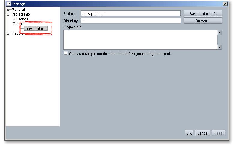
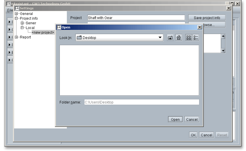
Please enter a project name into the input field ‘Project’. Click the button ‘Browse’ and save the file where the eAssistant calculation file is stored. Click the ‘Open’ button.
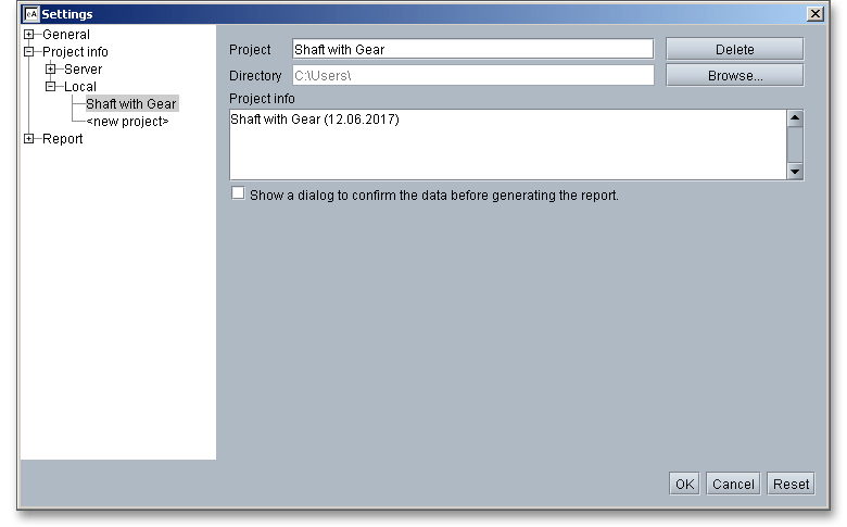
Add some text to the text field ‘Project info’. This text will appear in the header section of the calculation report. Click the button ‘OK’ in order to save your text.
Open a calculation module (e.g., for shafts). Now open the calculation file that is saved locally to your
computer.
Please note: When opening the calculation, please keep in mind to activate the option ‘Local’ in the top menu
bar of the calculation module.
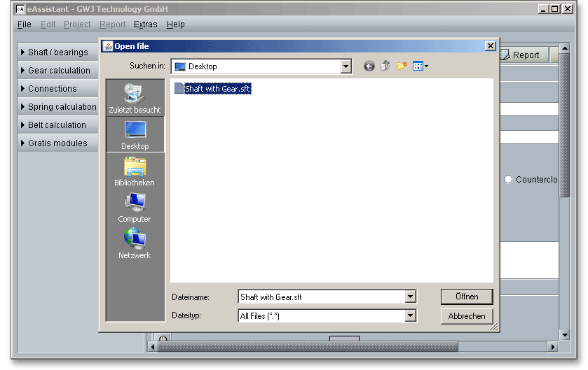
In order to generate the calculation report, click the button ‘Report’ in the calculation module. You can see the newly added text in the upper left corner. If you open the PDF calculation report, then the text will appear at the top of every page in your calculation report.
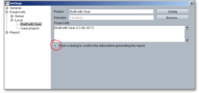
As with the menu item ‘Server’, you can activate the option ‘Show a dialog to confirm...’. If you check the checkbox, you receive a dialog each time before the generation of the calculation report starts. You can then decide whether to use the added project info or not. If this checkbox is clear, the calculation report is automatically generated and no prompt is displayed.
If you choose to place a check mark here, a message window will be opened each time before the generation of the calculation report begins. In this window you can check the project info again and decide if the text contains the information you want. If not, you can overwrite and quickly replace the text. Confirm with the ‘OK’ button and the calculation report including the new project info will be created. But the saved project info in the configuration manager cannot be overwritten and remains unchanged.
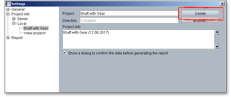
You can quickly and easily delete the local project info file from your computer. To do so, please click the the button ‘Delete’. The XML file automatically disappears from your computer.
The configuration manger provides report templates for each calculation module. Individual reports can be also integrated. If you have any questions or if you need further information, please feel free to contact us.
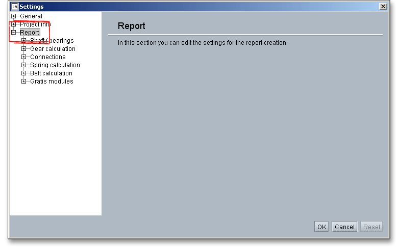
Click the tree view on the left-hand side to select a calculation module, for example shaft calculation. Click the listbox ‘Standard report template’ and choose either ‘Standard’ or ‘Short report’. Click on the button ‘Save settings’. If you select ‘Short report’, then a short report is generated for all calculation files that belong to the shaft module. A short report is not available for all calculation modules.
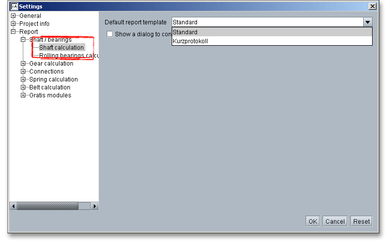
If you check the checkbox ‘Show a dialog to confirm...’, you receive a selection list each time before the generation of the calculation report starts. This list will help you decide which report template should be used for the report generation. If this checkbox is clear, the calculation report is automatically generated and no prompt is displayed.
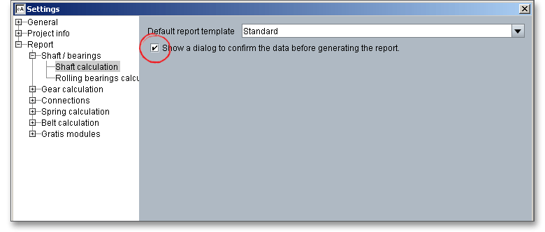
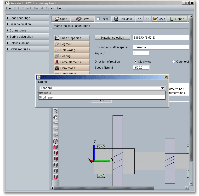
If you choose to place a check mark in the checkbox, a message window will be opened each time before the generation of the calculation report begins. In this window you can decide whether to create a standard calculation report or a short report. Confirm with the button ‘OK’ and the desired calculation report is generated.
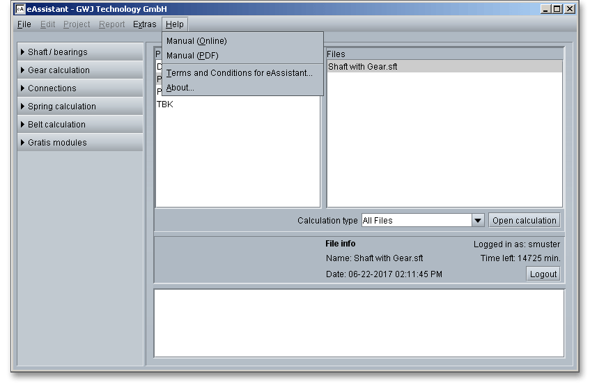
Click the button ‘Help’ to open the user manual in HTML and PDF format. It also contains the eAssistant Terms and Conditions.
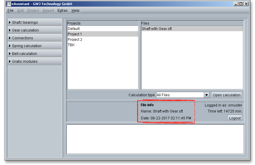
Here you get further information about the files. Click on a file, the ‘File info’ appears. You will get the name of the file, the calculation type as well as the date and time of your calculation that is saved to the eAssistant server.
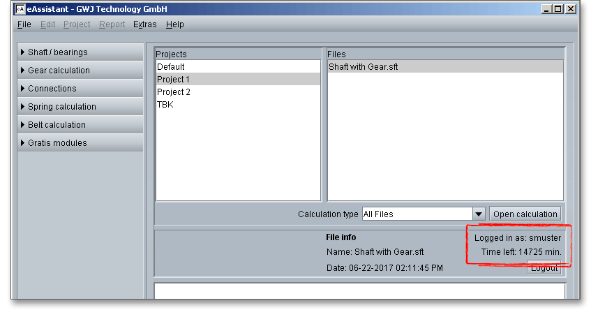
The time left is displayed in the information area. As long as you work in the project management, no time will
be lost or deducted from your account during this time. But when you open one of the calculation modules, the
usage time will be automatically deducted from your account. Please visit www.eAssistant.eu to get further
information.
Please note: The project management provides calculation modules for free: fit calculation according to DIN
ISO 286, shaft dimensioning according to Niemann, hardness conversion according to DIN 50150 as
well as a lubricant selection. When you start these modules from the eAssistant web site, it is not
necessary to register for the eAssistant. If you open the free modules using the project management,
no usage time will be deducted from your account. With flate rate accounts, the time is disabled,
too.
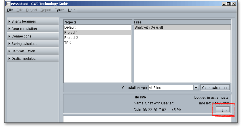
Click on the button ‘Logout’ to leave the program. You will be taken back to the login page and you can re-login.
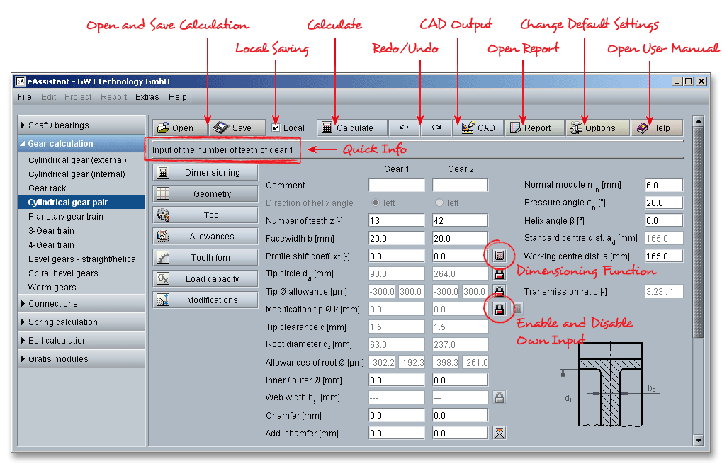
The top menu bar includes all general functions that are identical in every calculation module. Some calculation modules provide (e.g., shaft and cylindrical gear pair) the button ‘CAD’. Based on your calculation, parts can be generated automatically as a feature-based 3D part in a 3D system. Find more information in the calculation modules as well as in the section 3.16 ‘The Button CAD’.
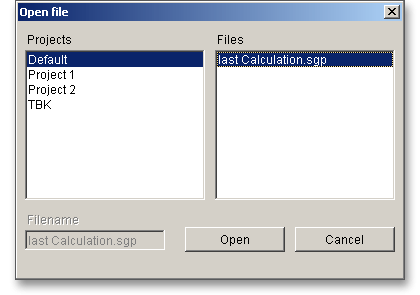
Click the ‘Open’ button in the top menu bar and choose the file that you want to open. Click the button ‘Open’.
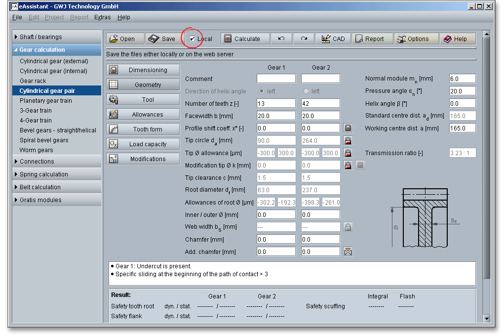
Activate the checkbox ‘Local’ and click the button ‘Open’.
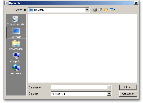
Select the file you want to open and click the ‘Open’ button.
In general there are two different possibilities to save a calculation. Save your calculation either to the eAssistant server or to your computer. Click on the button ‘Save’ to store the calculation to the eAssistant server. The checkbox „Local“ is not set.

A new window appears. Select a project where you want to save the file and type a name for the file. Click on the ‘Save’ button.
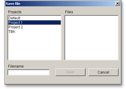
Please note: eAssistant identifies the calculation module automatically, so it is not necessary to specify the file
extension.
Activate the checkbox ‘Local’ and click the button ‘Save’.

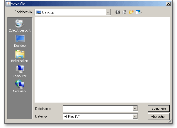
A standard Windows dialog for saving files will appear. Now you will be able to save the calculation to your computer.
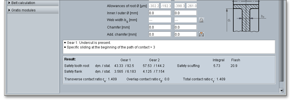
All results will be calculated during every input and will be displayed in the result panel. A recalculation occurs after every data input. Any changes that are made to the user interface take effect immediately. In case a minimum safety is not fulfilled, the result will be marked red. Press the Enter key or move to the next input field to complete the input. Alternatively, use the Tab key to jump from field to field or click the ‘Calculate’ button after every input. Your entries will be also confirmed and the calculation results will displayed automatically.

The button ‘Undo’ allows you to reset your inputs to an older state. The button ‘Redo’ reserves the undo.

The top menu bar of some calculation modules provides the button ‘CAD’. The CAD plugins for various CAD systems (e.g., SOLIDWORKS, Solid Edge, Autodesk Inventor, NX and Creo Parametric) offer a great way to connect calculation and design. Based on the eAssistant calculation, you can create shafts, cylindrical gears, bevel gears, involute splines, splined shaft or serrated shaft connections as a 3D part within seconds. The individual features of the CAD plugin depend on the CAD system. eAssistant also supports the output format DXF.

Before you can start using the CAD plugin, you need to download and install the plugin from our web site www.eAssistant.eu.
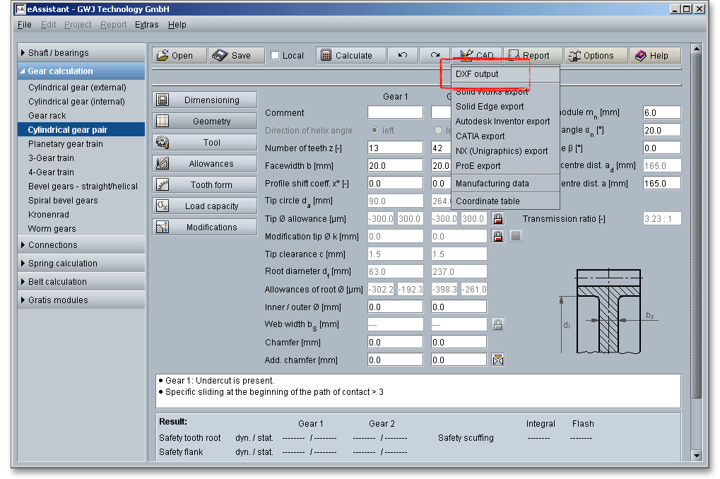
Click on the button ‘CAD’, then click on the menu item ‘DXF-Output’. An accurate tooth form for any involute gears in DXF format can be generated.
For the DXF output the following settings are possible:
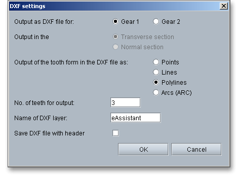
If you have changed your settings, then click on the button ‘OK’. A standard Windows dialog for saving the data file will appear.
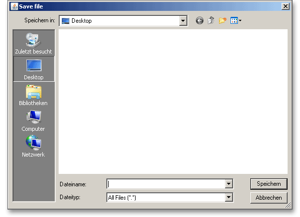
Now you can save the DXF file to your computer. Enter a name and click on the button ‘Save’. It is not
necessary to specify the file extension ‘dxf’, because the extension will be attached automatically to the file
name.
The CAD plugins for various CAD systems offer a great way to connect calculation and design. Together with the software, the CAD plugins allow to dimension, calculate and optimize various machine elements directly in the CAD system (SOLIDWORKS, Solid Edge, Autodesk Inventor, NX or Creo). The plugins enables the user to open all eAssistant calculation modules directly through the CAD menu. At the push of a button, the part can be created as a 3D part on the basis of the previously calculated data. First, you have to download and install the CAD plugin. You can find the plugin on our web site www.eAssistant.eu. After installation, an integrated button called ‘eAssistant’ appears in the CAD system.

Run the calculation using the eAssistant and click on the button ‘CAD’. Please select the appropriate CAD system from the list. The values are transferred to the CAD system where you can generate the 3D models through the eAssistant menu. By taking a step-by-step process defining the gears or pinions geometry, tolerances and tooth profile, you can create gears automatically as a 3D part. Based on the calculation, shafts with an unlimited number of cylindrical and conical segments can be created as a 3D part. The attractiveness of the CAD plugin is additionally enhanced by the bidirectional connection between eAssistant and the CAD system. As changes are made to a calculation, the 3D model can be updated. With just one click, the design table with all manufacturing details can be placed on the manufacturing drawing. The calculation information is saved in the 3D model and can be opened at any time throughout the entire design phase. Please visit www.gwj.de to get further information.
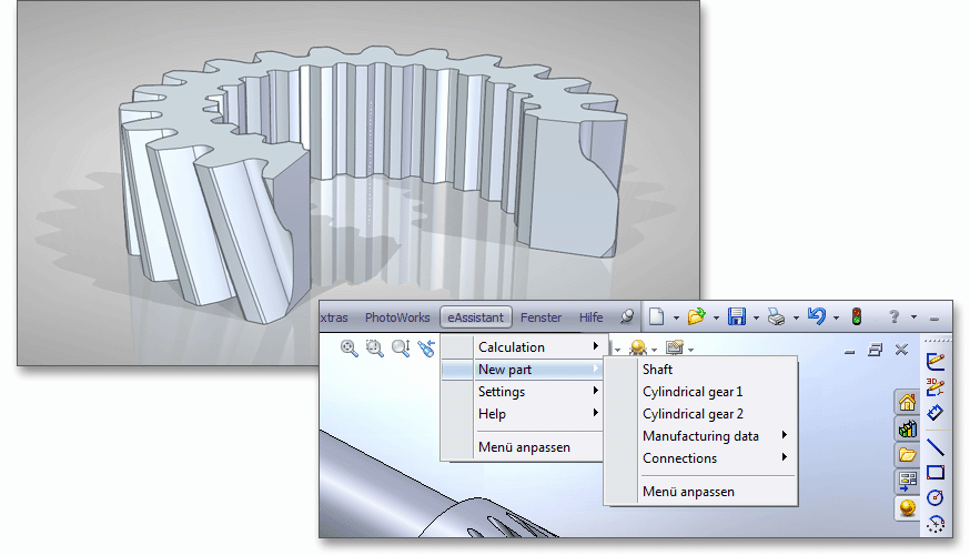
Please Note: Before you click the CAD button for involute gears, please click the button „Tooth form“. Select
„Detail view“ and set the desired allowance (min./middle/max).
The button ‘CAD \(\Rightarrow \) Manufacturing data’ allows to save the manufacturing data to a text file.

The gear tooth form geometry of a tooth space can be exported as a coordinate text file in transverse section as well as in normal section.

After the completion of your calculation, you can create a calculation report. Click on the ‘Report’ button.

You can navigate through the report via the table of contents that provides links to the input values, results and figures. This calculation report contains all input data, the calculation method as well as all detailed results. The report is available in HTML and PDF format. The calculation report saved in HTML format can be opened in a web browser or in Word for Windows. The reports are structured differently in the various calculation modules.
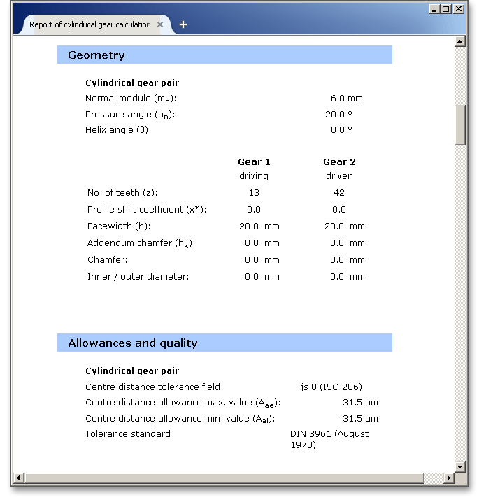
The calculation module includes:
Print, PDF or Save: Here you have the possibility to save and print the report or to generate a PDF document.
Some settings of the calculation modules have default values and by clicking the button ‘Options’ you can change these settings. For example, you can change the system of units, the minimum safeties for cylindrical gears, the operating temperature for springs or set the number of decimal places for the calculation report.

Click the button ‘Help’ to open the user manual. This takes you directly to the user manual of the respective module.

Every calculation module contains a message window. This message window displays detailed information, helpful hints or warnings about problems. One of the main benefits of the program is that the software provides suggestions for correcting errors during the data input. If you check the message window carefully for any errors or warnings and follow the hints, you are able to find a solution to quickly resolve calculation problems.

he quick info feature gives you additional information about all input fields and buttons. Move the mouse pointer to an input field or a button, then you will get some additional information. This information will be displayed in the quick info line.
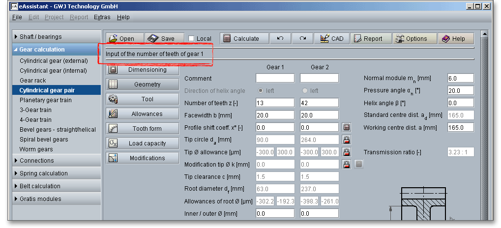
eAssistant provides two unit systems: the metric system and the U.S. customary unit system. You can quickly switch between the units. To select the unit system, click the button ‘Options’ and decide for a unit.
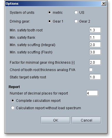
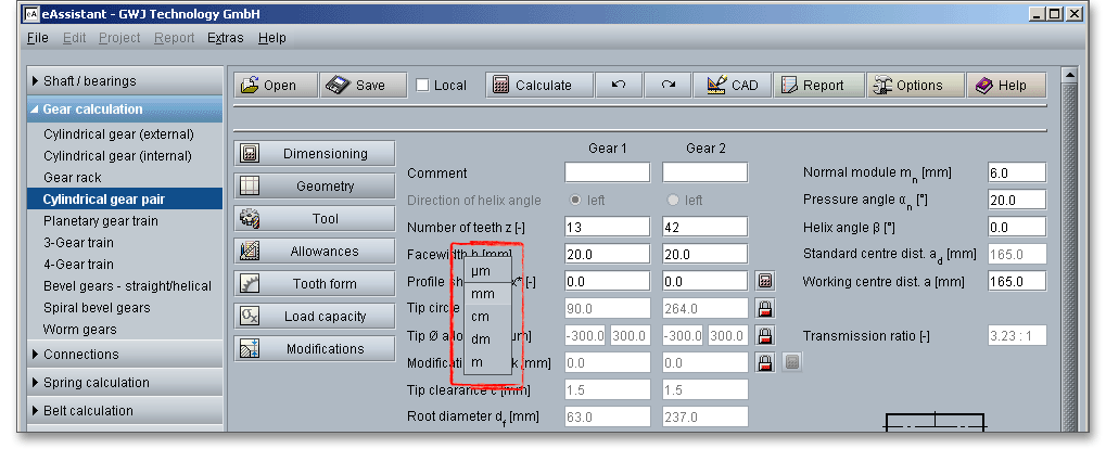
It is also possible to change the unit by clicking the label field. When you click the label field, a context menu will open providing all available units within the unit system. The change should take effect immediately. All settings will be saved to the calculation file. As soon as you select a unit, the current field value will be converted automatically into the chosen unit.
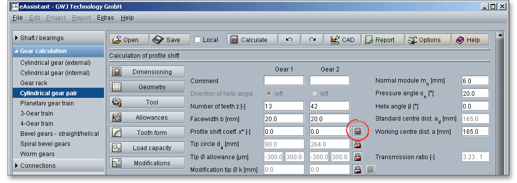
The button for the dimensioning functions is marked by a calculator symbol. Via the ‘Calculator’ button next to the input fields, you can have the program suggest appropriate values for you. In some modules, the maximum possible values are calculated by using the respective minimum safety.
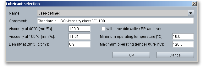
eAssistant enables you to specify your user-defined inputs. There you get the possibility to calculate non-standard parallel keys or to calculate involute splines which differ from the standard. In case you cannot find the material you are looking for in our extensive material database, you can define your individual material. You will find the entry ‘User-defined’ or the entry ‘User defined input’ in the listboxes. If you select one of these already mentioned options, the according input fields will be enabled, so that you can specify your own input values. Examples for the user-defined input:
Interference fit: Surface quality

Parallel key: Own input of load peaks

Roller bearings: Lubricant selection
Cylindrical gear pair: Selection of basic rack tooth profile

In some calculation modules (e.g., spur gear pair or parallel key module) you will find question mark buttons. If you click on these buttons, you will get additional information, for example figures or tables.
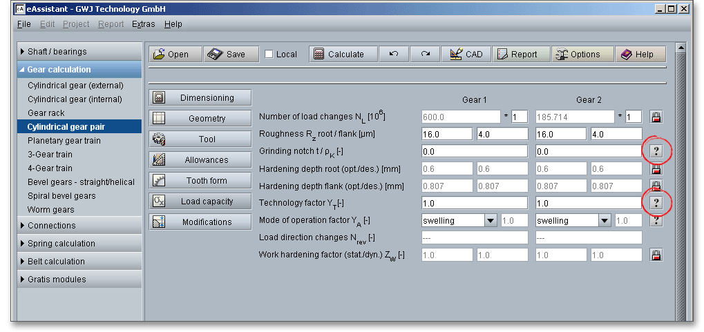
All results will be calculated during every input and will be displayed in the result panel. A recalculation occurs after every data input. Any changes that are made to the user interface take effect immediately. In case a minimum safety is not fulfilled, the result will be marked red. Press the Enter key or move to the next input field to complete the input. Alternatively, use the Tab key to jump from field to field or click the ‘Calculate’ button after every input. Your entries will be also confirmed and the calculation results will displayed automatically.
If you have to enter the same data very often, we recommend you to define a template file. That saves both time and work. All you have to do is to define a template. Enter your input data once into the calculation module. When you are ready to save the file, please name it ‘standard’. If you now open the calculation module, the module starts with your individual values. Please note that the template file can be saved only to the eAssistant server. You can define a template file specifically to a project or you can save the template file to the folder ‘Default’ for a general use. It is possible to define a template file for each calculation module. The default search follows the following order:
The template file, which was found first, is taken over. For example: If a template file is defined in the current
folder, then the file will be primarily accepted. But in case this template file does not exist, the file will be
searched in the project folder ‘Default’. There the template file is taken over again. If the file also cannot be
found there, then the central eAssistant standard is used.
Start the calculation module ‘Parallel key’. Change and define your input data. Click on the button ‘Save’ and select a project folder to save the file. Now enter the file name ‘standard’ into the input field.
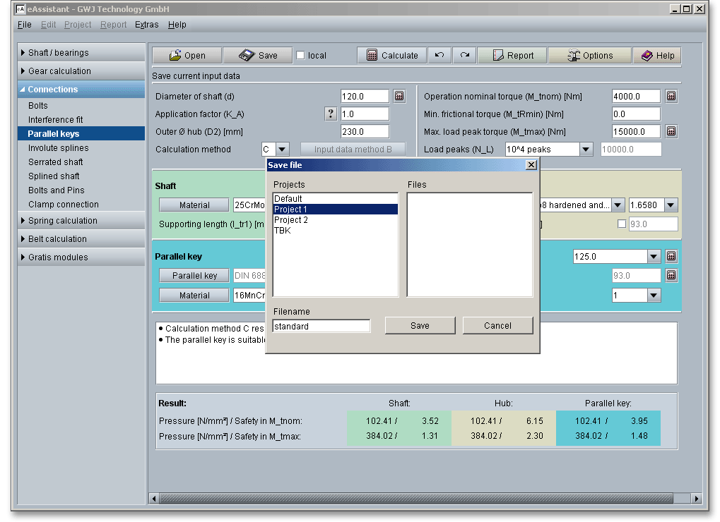
Please Note: It is not necessary to specify the file extension. The eAssistant identifies the calculation module automatically.
If you select the project ‘Default’, the template file applies for all projects, except for the projects where a template file was defined separately. Please also pay attention to the lower case of ‘standard’.
Close the calculation module ‘Parallel key’.
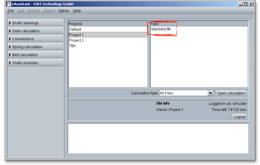
The calculation file ‘standard’ appears in the window ‘Files’. When you open the module ‘Parallel key’, the module starts with your previously defined values.