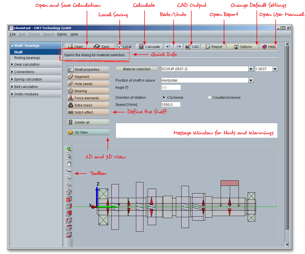
Please login with your username and your password. To start the calculation module for shafts, please click the menu item ‘Shaft/Bearings’ on the left side and select ‘Shaft’.

This module provides a geometry and a calculation part. The geometry part is the part where you define the
shaft geometry, the bearings, the loads as well as the notch effects. The actual calculation then takes place in
the calculation part. The calculation part allows to determine bearing forces, deflection, strength
or static torsion. Click on the ‘Calculate’ button to switch between the geometry and calculation
part.
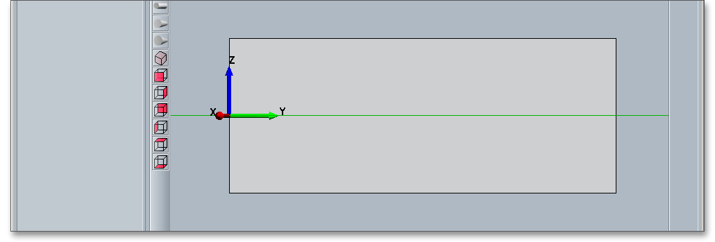
The geometry part allows you to define the entire shaft geometry including bearings, force elementes and force effects. The upper part of the module provides different input options. The lower part includes the coordinate system as well as the shaft symmetry axis. The input values are taken over immediately and are represented graphically in the lower part. The representation is interactive. That means, you can select, move, copy or delete shaft elements. Use the ‘3D’ view button to move quickly between 2D and 3D view.
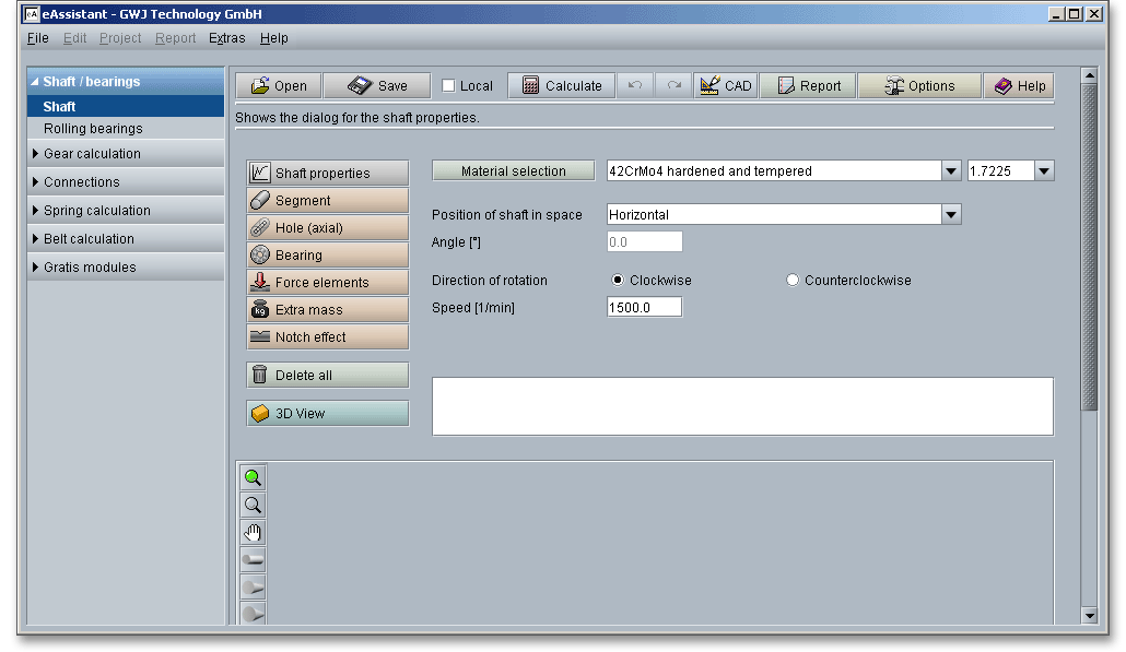
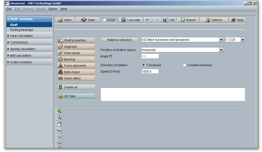
When you start the calculation module, the general shaft properties are automatically displayed. Use the ‘Shaft properties’ button to modify the properties at any time you want.

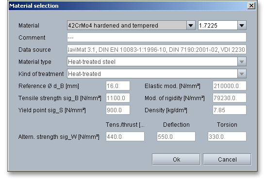
The shaft properties allows you to select the shaft material. You can also specify your own material. Define speed, direction of rotation and the position of the shaft in space. The speed is defined as revolutions per minute. Please keep in mind: When you change the speed of the shaft, the torques will change because of the entered power and speed. This happens when a power instead of a torque is given for the force elements. Select the material by using the listbox or material number. Click the button ‘Material selection’ and you get detailed information on the material (e.g., material type, density, yield point).
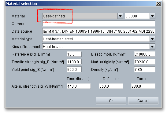
In case there is no material that will fulfill the design requirements, then simply define your individual material. Select ‘User-defined‘ from the listbox and click the button ‘Material selection’ or click directly on the button ‘Material selection’ to open the material database. Select the option ‘User defined’ and all inputs and options are enabled and you can specify your individual material very easily. Click on the button ‘OK’ to confirm your entries and to return to the shaft geometry part. Please be advised that changing the material will delete your defined inputs and you have to enter the inputs again.
Please note: It is important to consider the fact that the integrated strength calculation according to DIN 743 is
valid or steels only.
The calculation module uses a coordinate system that is a clockwise system where the Y-axis is the axis of symmetry as well as the axis of rotation of the shaft. In the two-dimensional view, the Z-axis shows upwards and the X-axis shows out of the screen. A rotation of the shaft around the Y-axis is defined as a clockwise rotation. The left end of the shaft is the point of origin. The forces and torques have to be entered in positive direction without signs and in negative direction with a minus sign.
Please Note: The direction of torques is usually defined by the input ‘driving’ and ‘driven’. The input ‘driving’ means that the shaft is driving and the torque counteracts the direction of rotation.

You get more information about the respective elements, for example about the absolute position. It is important that you have to differentiate between a relative position and an absolute position.

The positioning of an element occurs always from a shaft section related to the left side of the element. This means that the relative position corresponds to the input value ‘Position’ of the respective element.

The position of an element is displayed from the origin of the coordinate system to the left side of the element.

There are segments for the outer contour and axial holes for the inner contour available. Click on the button ‘Segment’ to create a shaft segment.

The segment is represented.

Input fields for the entry of length and diameter are displayed. To add a conic segment, activate the option ‘Conic segment’.

If this option is activated, enter a left diameter ‘1’ and a right diameter ‘2’ for the segment. To add another
segment, please click on the ‘Segment’ button again.
To create a hole (an inner contour), click on the button ‘Hole (axial)’. The different possibilities for a data input are now displayed.

In addition, you can extend the axial hole by clicking the button ‘Adjust to shaft length’. This button adapts the length of the axial hole to the shaft length automatically. Then the entire inner contour goes exactly to the end of the outer contour.

Please Note: For the strength calculation notch effects, such as shoulders, are not considered in the inner contour. There is no applicable calculation method right now.
You can add as many bearings as you need. A calculation of statically over-determined shafts with more than two bearings is possible. Select a shaft segment to position the bearing on the shaft, then click on the button ‘Bearing’.
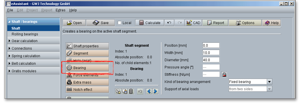
Now the bearing is added to the shaft.

To define the bearing, different options for an input are available: position, width, diameter, stiffness, and pressure angle. Further you can define the kind of bearing arrangement: fixed bearing, movable bearing, axial bearing or floating bearing.

Please note that the position refers to respective shaft segment, that means a relative position
has to be entered. The absolute position, related to the point of origin and with it related to the
left end of the shaft, is indicated with the element info (see section 4.2.3 ‘Relative and absolute
position’).
The width is the overall width of the bearing and the diameter is the outer diameter of the bearing for the
correct representation. For bearings with a pressure angle the changed point of application of load
can be considered for the calculation of the support reactions. In case the (radial) stiffness of the
bearing is known, the stiffness can be considered by appropriate settings for the calculation as
well.
Please Note: Bearings cannot be positioned over a shaft segment.
The shaft module offers different possibilities to define loads. Besides a direct input of forces and torques in
coordinate direction, so-called intelligent elements for application of load can be positioned on the shaft. Click on
the ‘Force elements’ button and you can select cylindrical gear, bevel gear, coupling/motor and
load.
At first select the shaft segment on which you want to create the cylindrical gear. Click on the button ‘Force elements’ and select the menu item ‘Cylindrical gear’.
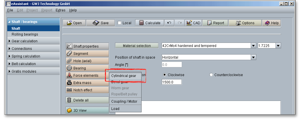
The cylindrical gear is added to the shaft.
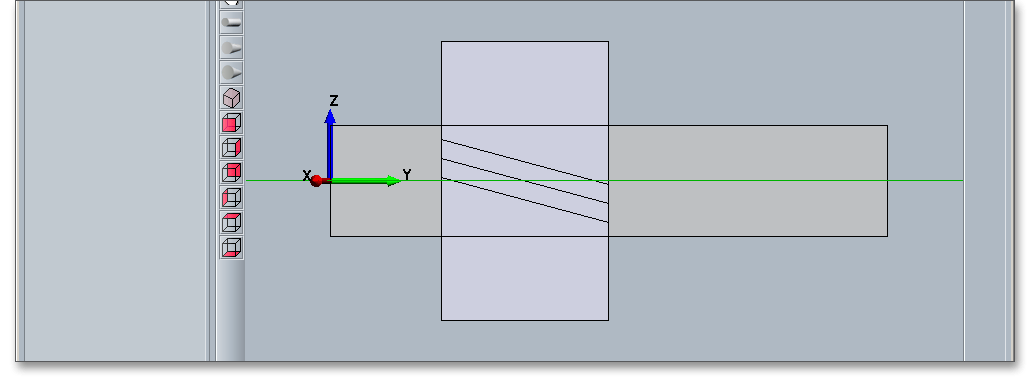
For the positioning of the shaft, the relative position of the left shaft side is given. Based on further inputs for pitch circle, helix angle, pressure angle, position of action and power/torque, the calculation of forces, that influence the shaft, is determined.

In particular the input of power of action is important for the point of application of load. The power of action indicates the position of the point of the interference with the gear pair.
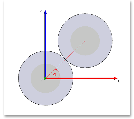
For cylindrical gears with a profile shift modification, reference circle and pitch circle are not equal. When you
enter the reference circle of the cylindrical gear, the calculated forces are not completely accurate - in particular
with very large profile shift modifications. For an exact calculation of the forces, you have to enter the pitch circle
diameter instead of the reference diameter and instead of the pressure angle you have to enter the working
transverse pressure angle.
The ‘T/P’ button allows you to enter either the power or torque. The description of the input field will be changed accordingly in torque or power.

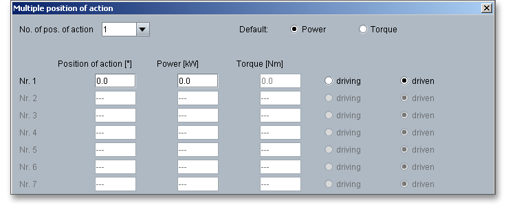
Here you can define a multiple position of action, that means that the cylindrical gear, which is on the shaft, is in mesh with several cylindrical gears. Set a checkmark into the field next to ‘Use multiple position of action’ and click on the button ‘Multiple position of action’.

Select the number of position of action from the listbox. Further you can indicate either ‘Power’ or ‘Torque’. Confirm your inputs with the button ‘Ok’.
If two helical gears are in mesh, both gears have the same, but opposite direction of the helix angle \(\beta \). The direction of the helix angle has to be opposite that a left-hand mates a right-hand. Therefore, you have to differentiate between right-handed helix angle and left-handed helix angle. Please specify here right or left-hand helix angle.

A driving gear and a driven gear always co-operate and form a gear pair. For the most force elements the direction of torques is specified by the input of driving and driven. The input ‘driving’ means that the shaft drives or that the moment counteracts the direction of rotation.
Define here the driving and driven cylindrical gear. You can also define it with the ‘Multiple position of action’.

To add a bevel gear, please mark the shaft segment onto which you want to generate the bevel gear. Then click on the button ‘Force elements’. Select the menu item ‘Bevel gear’.

The bevel gear is added to the shaft.
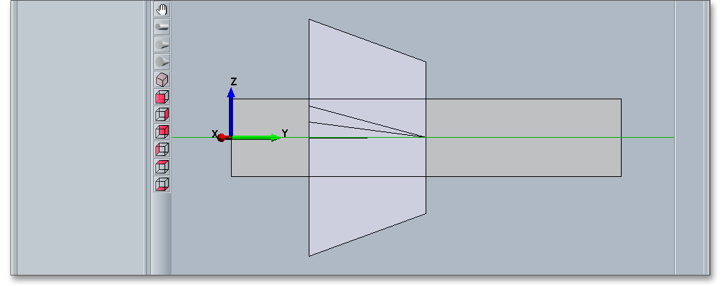
When you add a bevel gear, additionally inputs are available, for example an input for a bevel angle or for the direction of the bevel angle.

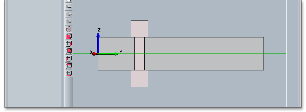
The force element ‘Coupling/Motor’ allows the input and output of torques. Just like the spur and bevel gears you can enter a mass additionally. The positioning occurs relative to the selected shaft segment. The position refers to the left side of the force element. First select a shaft segment to position the force element.

The coupling is added to the shaft.
The general force element ‘Load’ can be positioned freely on the shaft independently from a selected shaft segment. Click on the button ‘Force elements’ and select the menu item ‘Load’.

The load is added to the shaft.

The specification of the position occurs absolutely to the point of origin (left shaft end) and refers, like the other elements, to the left side of the element.

The element can be defined as a concentrated load (width = 0) or as a stretch load. This general force element offers the possibility to specify lateral forces in X and Z-direction, a axial forces as well as bending moments around the X and Z-axis as a load. Further you can define the power or the torque as driving and driven. The meaning of driven and driving applies here similarly to the other force elements.
The button ‘Extra mass’ allows you to add a several mass.
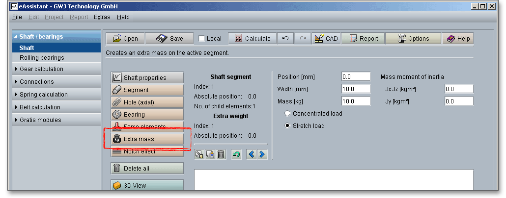
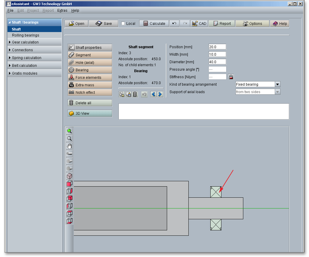
Please enter here position, width and mass. An extra mass can be defined as a concentrated load or as a stretch load.
The definition of notch effects is necessary for the strength calculation according to DIN 743. In case you have calculated the equivalent stress before, then it is not necessary to enter all notch effects. Based on the tension peaks, which appear in the process of the equivalent stress, the critical cross sections can be identified very easily and the notch factors can be defined only for these cross sections. All defined types of notch effect according to DIN 743 are available.
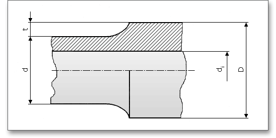
The notch factors defined in DIN 743 apply to solid and hollow shafts with wall thicknesses where no interference of the notch by the hole is existing. For rotating notches the condition is used, according to DIN 743-2 (field of application),
\[\frac {D-d_{i}}{2\times t}\geq 3\]
for orientation (q.v. DIN 743-1, Appendix A)
When adding a notch effect, please select the shaft element and click the button ‘Notch effects’.
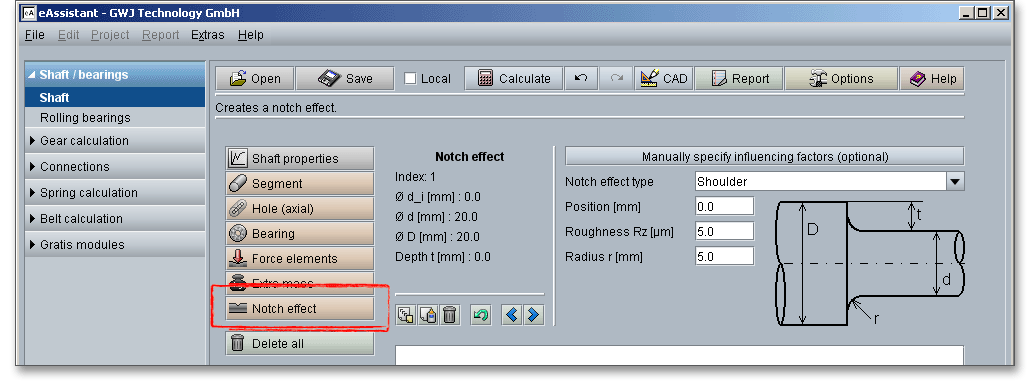
The notch effect is added to the shaft.

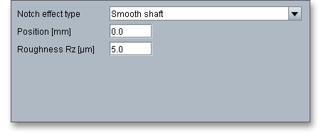
To run a strength calculation for highly loaded smooth shafts, select the notch effect ‘Smooth shaft’ from the listbox. For this type of notch effect, the notch factor is set to ‘1’. Notch effects can be placed easily on the shaft, independent of a shaft segment. The notch effects can be positioned absolutely to the point of origin (to the left shaft end).
You can enter the exact position into the input field ‘Position’, use the two arrow keys to move the notch effect from one shaft section to the other shaft section. With the left mouse button it is easy to place the notch effects on the shaft.

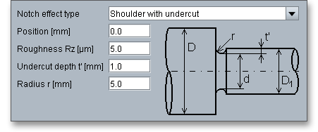
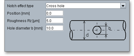
Select the following types of notch effects from the listbox:
- Smooth shaft and parallel key keyway
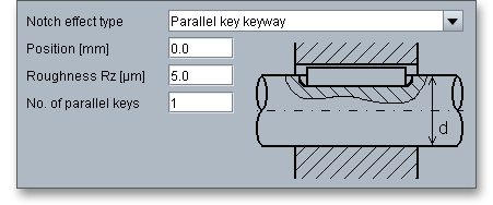
- Interference fit and splinded shaft
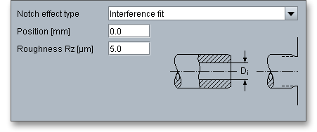
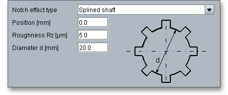
- Serrated shaft and involute splines
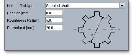
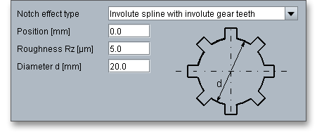
- V-groove and square groove
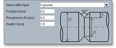
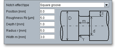
- Shoulder and round groove
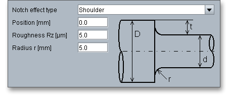
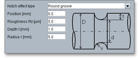
- Shoulder with undercut and cross hole
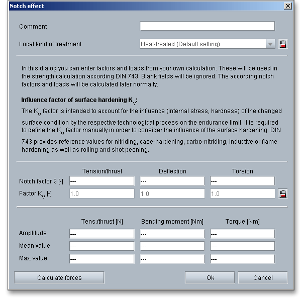
The button ‘Set load and notch factors manually (optional)’ allows you to enter notch factors manually (in addition to the automatic calculation of the notch factors). Here the possibility exists to use experimentally calculated notch factors.

Click the button ‘Set load and notch factors manually (optional)’, the following window opens.
For overlapping notch effects (two notches with notch factors \(\beta _{1}\) and \(\beta _{2}\)), the notch factors can be estimated according to Niemann ‘Maschinenelemente’ Vol. 1, page 134, equation 3.115 (3rd Edition) as follows:
\[\beta = \beta _{1} + \beta _{2} - 1\]
Please note that you cannot use the notch factors according to DIN 743 for notches on the inner
contour.
Use your left mouse button to select the shaft or force elements. When choosing an element, the color of the
selected element changes and it is easier to recognize it.
Please Note: It is also possible to select individual elements by using your keyboard. If you would like to
change, for example from the value input of shaft segments to the selection mode, you have to
press the ‘Page-down’ key. Afterwards, the two arrow keys enable you to move the elements to the
left or to the right side. To move from the shaft segments to the axial hole, please use the cursor
keys ‘Up’ and ‘Down’. By using the ‘Page-up’ key you can change to the input value of a selected
element.
If an element is selected, then different input possibilities for the element appear in the upper area of the calculation module. The input field ‘Position’ helps to place an element on the shaft. For positioning the element, you can also click on an element, continue holding the left mouse button and then drag the mouse. The arrow keys below the element info allows you to move to the next segment. It is possible to skip certain elements on the shaft. If a shaft segment is selected, then the segment can be shifted using the arrow key including all elements sitting on the segment. Thus, you can easily re-sort shaft segments.

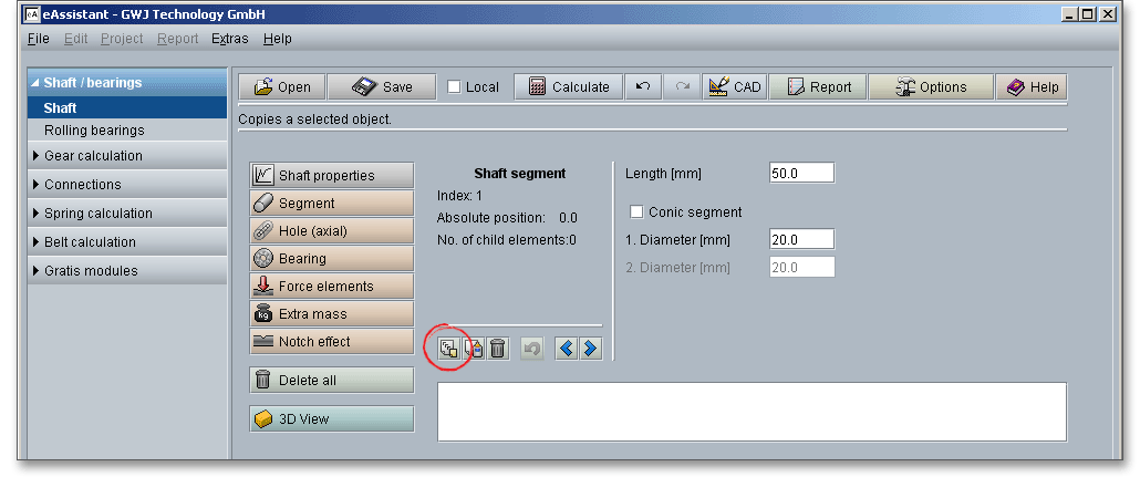
The two buttons ‘Copy’ and ‘Add’ allow to copy and add segments, bearings or force elements. If you copy an element, all inputs will be confirmed and you do not have to re-define the element again. Place the element by using the input field ‘Position’ or by clicking or dragging your left mouse button or by clicking the arrow keys on your keyboard.

Select an existing bearing which you would like to copy.

Click on the button ‘Copy’.

Select the shaft segment on which you would like to place the bearing.

Click on the button ‘Add’.

The previously copied bearing is added.

Please Note: If you select an element and click the right mouse button, a new context menu will open. Choose the menu items ‘Copy’ and ‘Add’.

Select a segment or an element and click the right mouse button to open the context menu. Choose the menu item ‘Cut out’.

This button allows you to delete an element. To delete an element, select the element and click the button ‘Delete’. You can also click the right mouse button to open the context menu and to select the menu item ‘Delete’.

Clicking the ‘Delete all’ button deletes not just one element but the entire shaft geometry. Right-clicking opens the context menu where you can select the menu item ‘Delete all’.

Clicking this button displays the three-dimensional presentation. This function is available in the geometry part as well as in the calculation part. Using this button, the deflection (inculding the selected planes) of the shaft can be visualized in a three-dimensional manner.

The three-dimensional view allows to modify the elements. Select the element and change, for example, the position, length or diameter. To do so, please use the appropriate input fields. Click on the ‘2D / 3D view’ button again to switch back to the two-dimensional representation.

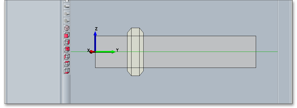
The toolbar on the left side contains buttons that let you toggle between different views of your shaft quickly. There are zoom options available that allow you to zoom in and out.

|
| Reset view and show the entire shaft |
|
| Activate zoom selection with mouse click: By dragging the cursor with the left mouse button, you can select parts of the shaft and enlarge them. Click the button ‘Reset view’, then you can restore the original view of the shaft. |
|
| Move view with mouse: Click into the graphical representation,hold the mouse button and move the shaft. |

|
| Orthogonal view |
|
| Perspective view |
|
| Perspective wide angle view |
|
| 3D view of the shaft from left upside |
|
| Frontal 3D view of the shaft |
|
| 3D view of the shaft from right |
|
| 3D view of the shaft from rear |
|
| 3D view of the shaft from left |
|
| 3D view of the shaft from upside |
|
| 3D view of the shaft from downside |
The calculation module provides a message window. This message window displays detailed information, helpful hints or warnings about problems. One of the main benefits of the program is that the software provides suggestions for correcting errors during the data input. If you check the message window carefully for any errors or warnings and follow the hints, you are able to find a solution to quickly resolve calculation problems.

The quick info feature gives you additional information about all input fields and buttons. Move the mouse pointer to an input field or a button, then you will get some additional information. This information will be displayed in the quick info line.

After defining the entire shaft geometry, bearings, loads and notch effects, you can start your calculation. To start the calculation, click the button ‘Calculate’. The button changes then its description into ‘Geometry’ and you get into the calculation part. The calculation part enables you to carry out the calculation. If you want to modify the geometry of the shaft, you have to go back to the geometry part. To do so, please click the button ‘Geometry’.
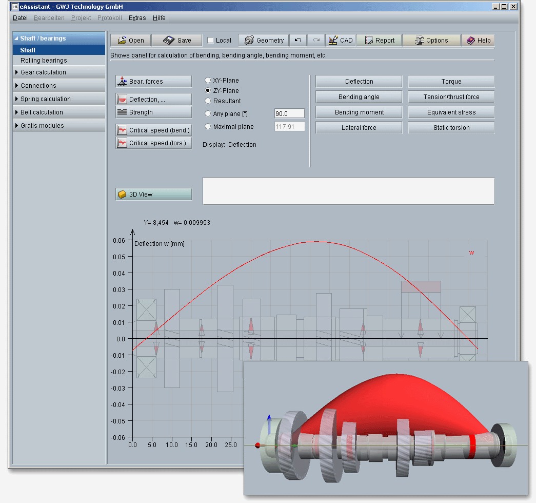
In addition to the determination of the bearing forces and static torsion, different diagrams for forces, moments, deflection, bending angle, equivalent stress or torque will be displayed. Move the mouse over the graphical representation to see the values for the deflection at any shaft position. With just one click, the following calculations can be carried out:

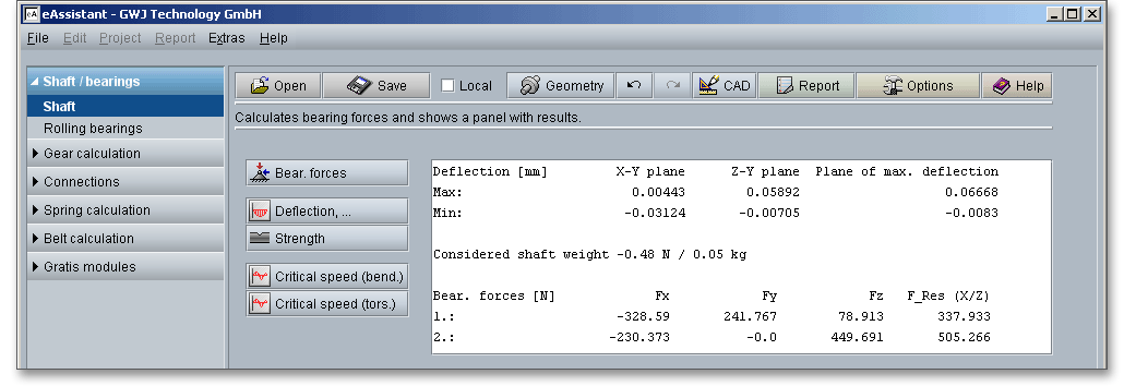
Click the button ‘Bearing forces’ in order to start the calculation of the bearing forces.
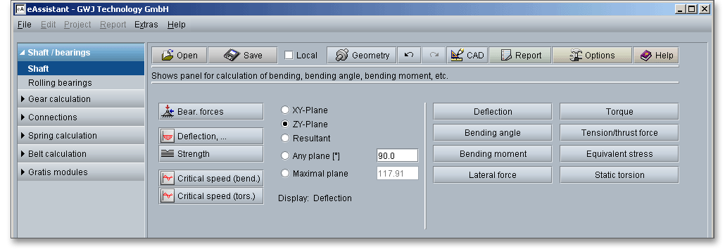
Click the button ‘Deflection’ in order to start the calculation of the deflection, bending angle and bending moment. Select the forces and moments for different planes.
The values for the deflection can be selected directly from the graphical representation. The values appear in the text field. Click the button 3D view to toggle between the 2D and 3D view.
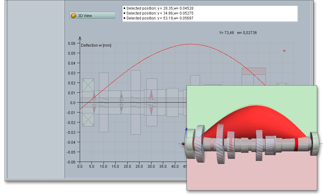
Please note: There is the possibility to compare different deflections (e.g., for shafts with a modified geometry)
based on the graphical representation. Go back to the geometry part and change a value. Click on the Calculate
button to go to the calculation part again. Click on the ‘Redo’ and ‘Undo’ buttons in the menu bar. Now you can
compare the results
Click the button ‘Strength’ in order to start the strength calculation. The strength calculation provides a complete static and fatigue proof of strength according to DIN 743. The exact values appear in the text field and can be selected with a mouse click from the graphical representation.
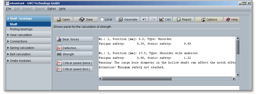
The calculation report provides all detailed calculation results. In addition, the results for the cross sections are represented in three different colors:
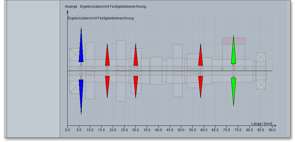
Please note: Click the button ‘Options’ to modify the settings for the minimum safety, the stress conditions and
mechanical kind of material treatment (see section 4.13 ‘The Button Options’).
Click the button ‘Critical speed (bending)’ in order to start the calculation of the critical speed. Gyroscopic effects, moments of inertia, deflection due to shear can be taken into consideration. To do so, please activate the appropriate checkbox.
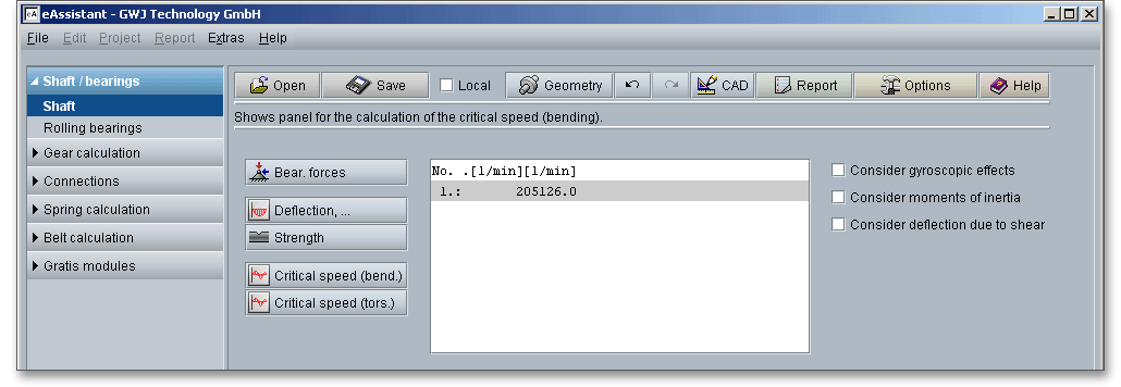
Click the button ‘Critical speed (torsion)’ in order to start the calculation of the critical speed.

Please note: Please click the button ‘Options’ to modify the default settings regarding the critical speeds (see
section 4.13 ‘The Button Options’).
After the completion of your calculation, you can create a calculation report. Click on the ‘Report’ button.

First the report configurator appears. The report configurator allows you to select which diagrams should appear in the calculation report and if the results of the strength calculation should be in the report, too.
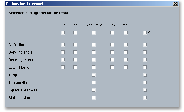
During the generation of the report, a waiting screen appears. But you can continue to work with the calculation module. The length of time for the generation of the report depends on the number of diagrams which have to be generated. You can navigate through the report via the table of contents that provides links to the input values, results and figures. This calculation report contains all input data, the calculation method as well as all detailed results. The report is available in HTML and PDF format. The calculation report saved in HTML format, can be opened in a web browser or in Word for Windows. In HTML format, the figures are displayed in ‘gif’ format. In case a SVG viewer is available, you can display all graphics in SVG format. Right-clicking on the picture allows to zoom in and zoom out.
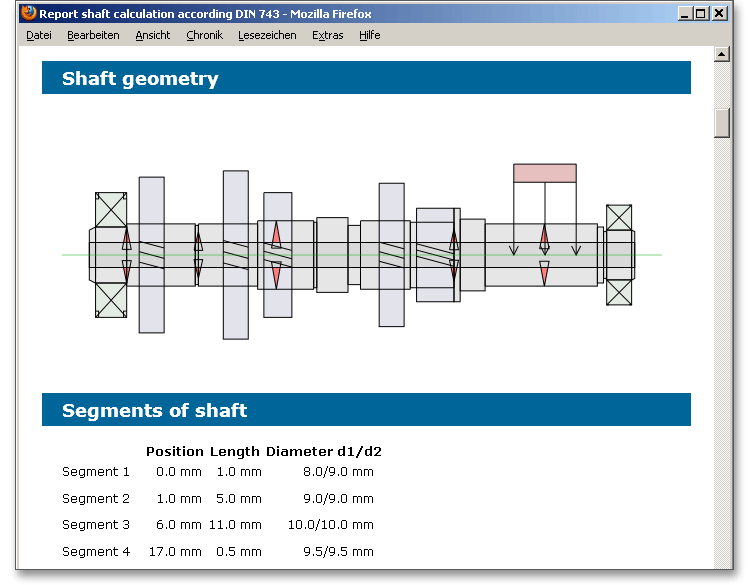
When the calculation is finished, it is easy to save the calculation. You can save your calculation either to the eAssistant server or to your computer. Click on the button ‘Save’.

Before you can save the calculation to your computer, you need to activate the checkbox ‘Local’ in the calculation module. A standard Windows dialog for saving files will appear. Now you will be able to save the calculation to your computer.
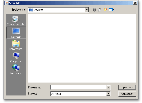
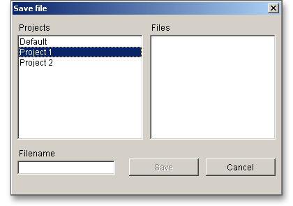
In case you do not activate the option in order to save your files locally, then a new window is opened and you can save the calculation to the eAssistant server. Please enter a name into the input field ‘Filename’ and click on the button ‘Save’.
The button ‘Undo’ allows you to reset your input to an older state. The button ‘Redo’ reverses the undo.

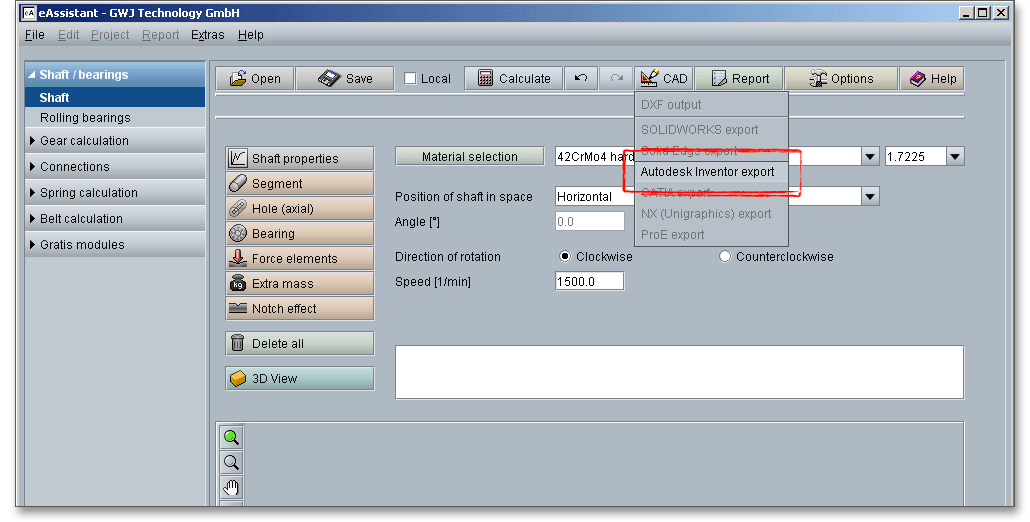
The top menu bar of the calculation module provides the button ‘CAD’.

The eAssistant plugin for various CAD systems (e.g., SOLIDWORKS, Solid Edge, Autodesk Inventor) enables
you to combine calculation and design fast and easily. Based on your eAssistant calculation, you can create the
shaft as a 3D part within seconds.
Solid and hollow shaft with an unlimited number of cylindrical and conical elements can be generated with just a click. Click the button ‘CAD’. Please select the appropriate CAD system from the list.
Open your CAD system. The top menu bar of the CAD system shows a button called ‘eAssistant’. Please click
this button to start the generation of the 3D model.
Please note: Before you can start using the CAD plugin, you need to download and install the plugin from our
web site www.eAssistant.eu.
A simple mouse-click allows to add all necessary manufacturing data of a gear wheel to the drawing.
In case you need further information about the eAssistant CAD plugin, please feel free to contact us. The web
site www.eAssistant.eu also contains detailed information. There you can also find the CAD plugin manuals
for the various CAD systems.
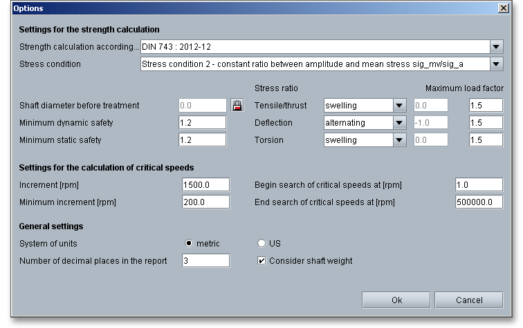
Click the button ‘Options’ in order to change the default settings for the strength calculation according to DIN 743 as well as for the calculation of the critical speeds.

Here are the default settings that you can modify:
Settings for the strength calculation according to DIN 743:
Settings for the calculation of the critical speeds:
Please login with your username and your password. To start the calculation module for shafts, please click the menu item ‘Shaft/Bearings’ on the left side and then select ‘Shaft’.
This calculation example shows a winding shaft with a fixed and movable bearing and an extra mass.
Click the button ‘Segment’ in order to create the first shaft segment. Enter a length of 50 mm and a diameter of 20 mm into the input fields.

The first segment is represented.
To create the second shaft segment, click the button ‘Segment’ again. The second segment has a length of 400 mm and a diameter of 50 mm.
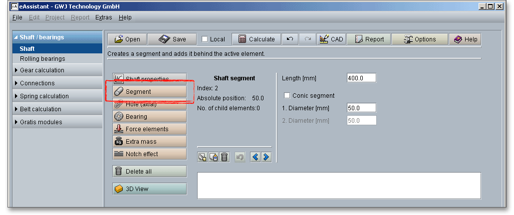
This second segment is represented.
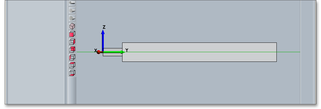
The third shaft segment gets the same dimensions as the first shaft segment. That is why we can use the ‘Copy’ and ‘Add’ function to create the third segment. Click on the first segment.
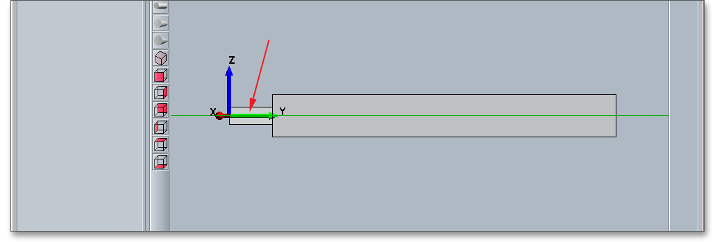
Click on the button ‘Copy’.
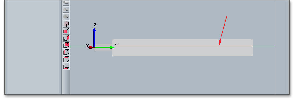
Select the second segment and place the third segment next to it.
Click on the button ‘Add’.
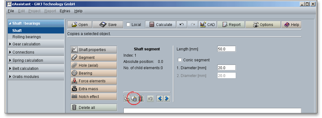
The copied segment is added as a third shaft segment.
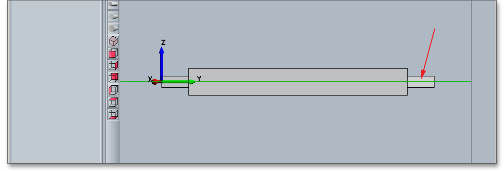
Please note: If you select a segment and you click the right mouse button, a new context menu will open.
Choose the menu items ‘Copy’ and ‘Add’.
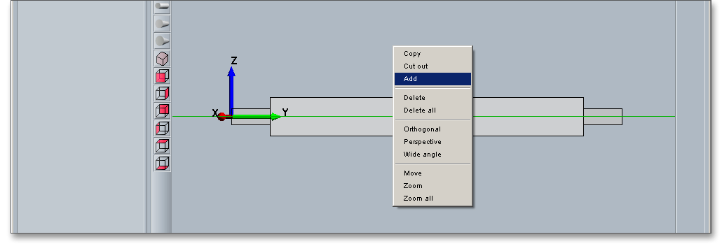
Click the button ‘Hole (axial)’ in order to create the first hole. Enter a length of 70 mm and a diameter of 0 mm into the input fields.

Click the button ‘Hole (axial)’ again in order to create a second hole. Enter a length of 360 mm and a diameter of 40 mm into the input fields.

The hollow shaft is represented.
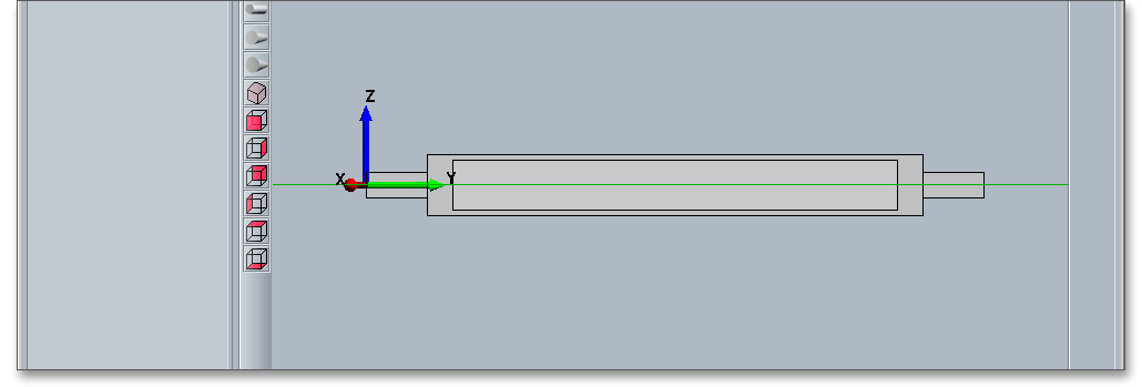
Please note: Use your keyboard to select the individual elements. For example, if you want to change from the
value input of a shaft segment to the selection mode, then press the ‘Page down’ key. Then use
the two arrow keys to select the elements. Use the cursor keys ‘Up’ and ‘Down’ to move from the
shaft segments to the axial holes. In order to change the input values of an element, press ‘Page
up’.
Select the first shaft segment to add the bearing to the shaft.

Click on the button ‘Bearing’.
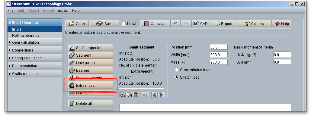
A bearing is added. Enter 20 mm for the bearing position, 10 mm for the bearing width and 40 mm for the bearing diameter. As bearing arrangement, select ‘Fixed bearing’ from the listbox.

In order to add the second bearing, select the first bearing and click the button ‘Copy’.

Select the third shaft segment and click the ‘Add’ button. Because the bearing is copied, it is not necessary to define the position, width and diameter of the bearing, you just need to define the bearing arrangment. Select ‘Movable bearing’ from the listbox.
To position the load, select the second shaft segment.

Click on the button ‘Extra mass’.
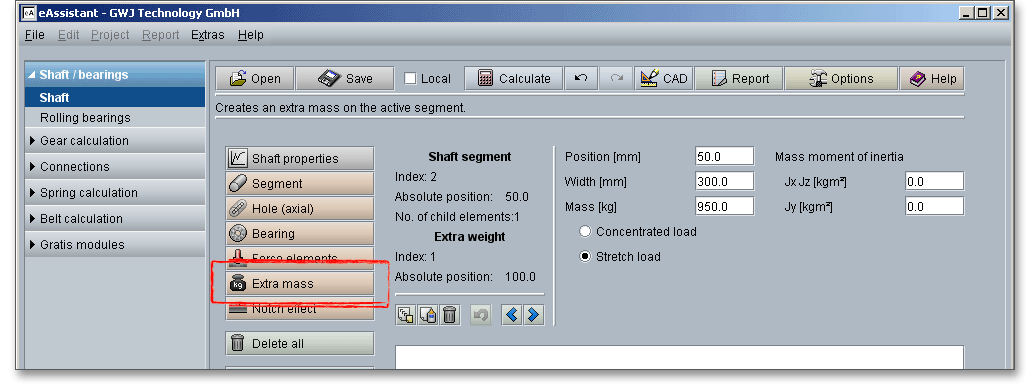
The extra mass will be positioned on the shaft segment. Please define the extra mass with 50 mm for position, 300 mm for width and 950 kg for mass.
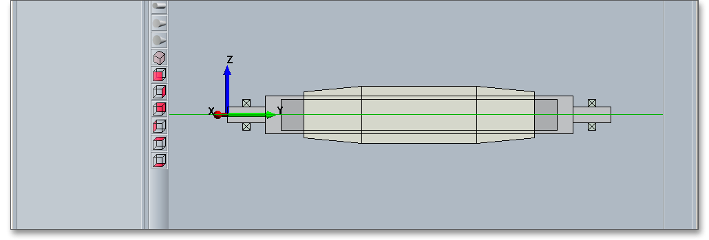
Click on the button ‘Notch effect’ in order to add the notch effects.
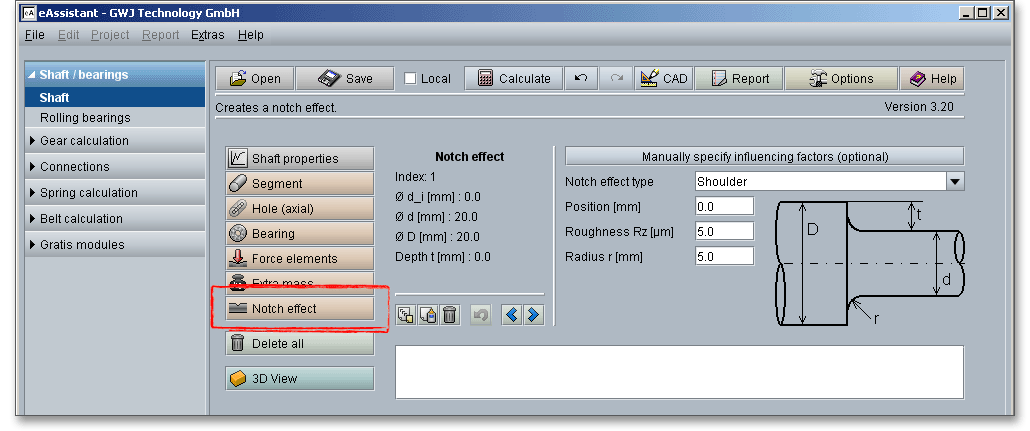
A notch effect is added and can be placed on the shaft. Enter the position of the notch effect or change the postion with the two arrow keys. Selct the notch effect from the listbox.
Define the following notch effects:
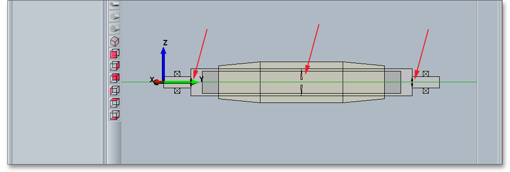
After defining the entire shaft geometry with bearings, loads and notch effects, you can start your calculation. To start the calculation, click the button ‘Calculate’. The button changes then its description into ‘Geometry’ and you get into the calculation part. The calculation part enables you to carry out the calculation. If you want to modify the geometry of the shaft, you have to go back to the geometry part. To do so, please click the button ‘Geometry’.
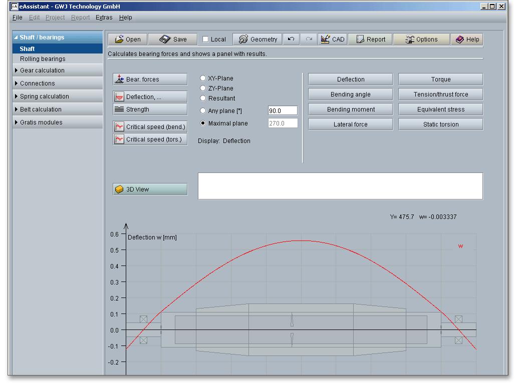
When you are in the calculation part of the module, it is not possible to change the geometry. In order to change the geometry, please go back to the geometry part by clicking the ‘Geometry’ button.
Here, you can carry out the different calculations, e.g., the strength calculation according to DIN 743.

In order to start the calculation of bearing forces, click the button ‘Bearing forces’.
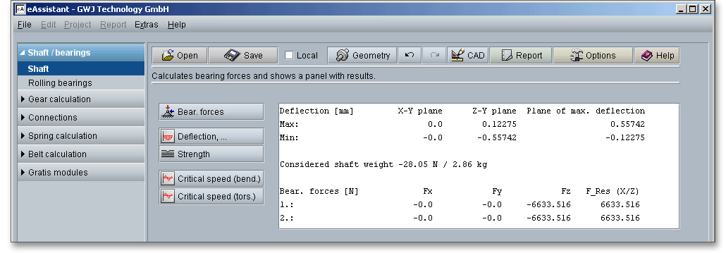
Click the button ‘Deflection’ to start the calculation of the deflection, bending angle and bending moment. Open the different diagrams for forces and moments.
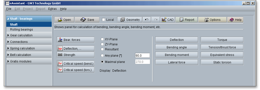
You can select all values for deflection directly from the representation with just a mouse click. The values appear in the text field.

Start the strength calculation by clicking the button ‘Strength’. The strength calculation provides a complete static and fatigue proof of strength according to DIN 743. The exact values appear in the text field and can be selected with a mouse click from the graphical representation.
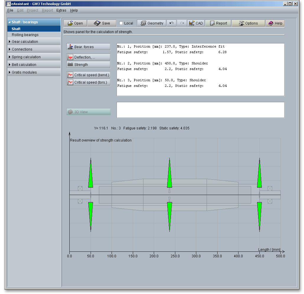
The text field shows the most important calculation results. The calculation report provides all detailed calculation results. In addition, the results for the cross sections are represented in three different colors:
Start the calculation of the critical speeds by clicking the button ‘Critical speed (bending)’. Gyroscopic effects, moments of inertia, deflection due to shear can be taken into consideration. To do so, please activate the appropriate checkbox.
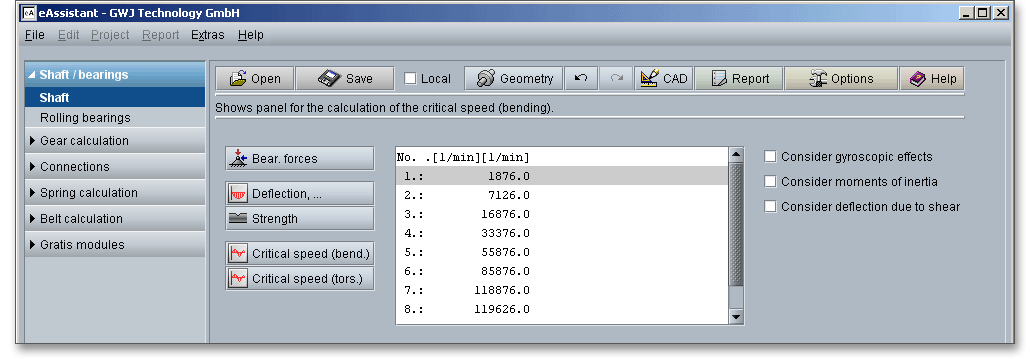
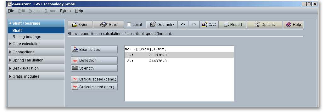
Click the button ‘Critical speed (torsion)’ in order to start the calculation of the critical speed.
Now you can create the calculation report. Click on the button ‘Report’.

First the report configurator appears. The report configurator allows you to select which diagrams should appear in the calculation report and if the results of the strength calculation should be in the report, too.
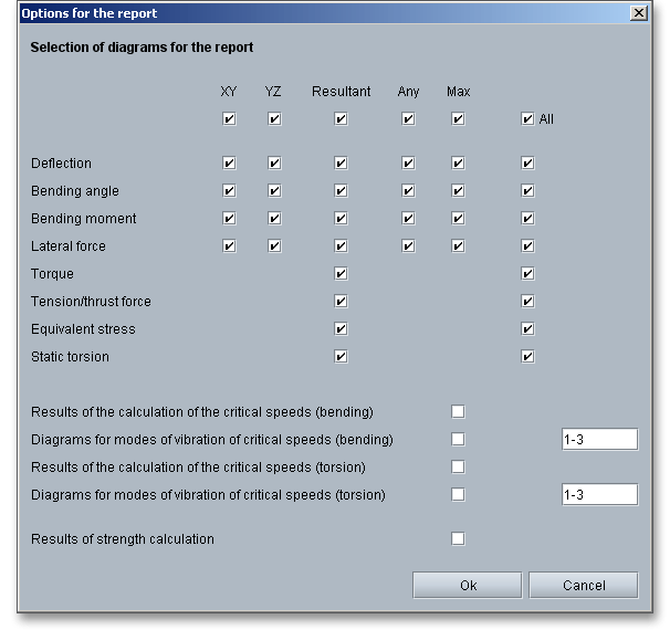
During the generation of the report, a waiting screen appears. During the generation of the report, a waiting
screen appears. But you can continue to work with the calculation module. The length of time for the generation
of the report depends on the number of diagrams which have to be generated.
You can navigate through the report via the table of contents that provides links to the input values, results and figures. This calculation report contains all input data, the calculation method as well as all detailed results. The report is available in HTML and PDF format. The calculation report saved in HTML format, can be opened in a web browser or in Word for Windows. In HTML format, the figures are displayed in ‘gif’ format. In case a SVG viewer is available, you can display all graphics in SVG format. Right-clicking on the picture allows to zoom in and zoom out.
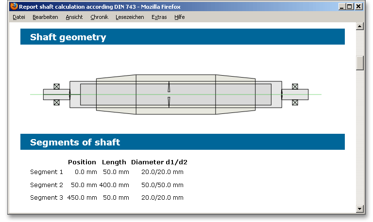
You may also print or save the calculation report:
When the calculation is finished, it is easy to save the calculation. You can save your calculation either to the eAssistant server or to your computer. Click on the button ‘Save’.

Before you can save the calculation to your computer, you need to activate the checkbox ‘Local’ in the calculation module. A standard Windows dialog for saving files will appear. Now you will be able to save the calculation to your computer.
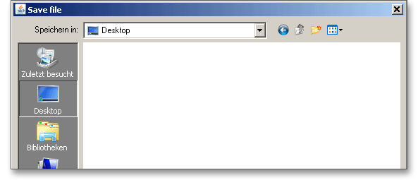
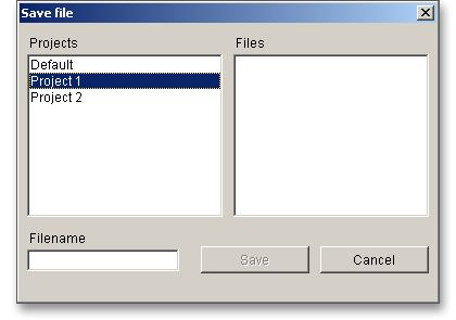
In case you do not activate the option in order to save your files locally, then a new window is opened and you can save the calculation to the eAssistant server. Please enter a name into the input field ‘Filename’ and click on the button ‘Save’.
Here you find another example that shows how easy it is to create a shaft.
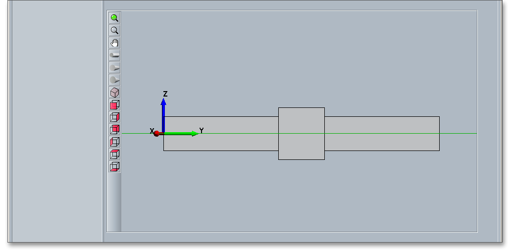
Create three shaft segments. Please enter the following input values:
| 1. Shaft segment: | Length \(l_{1}\) = 100 mm | Diameter \(d_{1}\) = 30 mm |
| 2. Shaft segment: | Length \(l_{2}\) = 40 mm | Diameter \(d_{2}\) = 45 mm |
| 3. Shaft segment: | Length \(l_{3}\) = 100 mm | Diameter \(d_{3}\) = 30 mm |
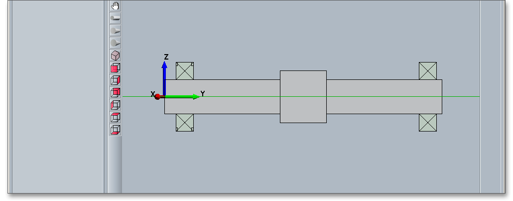
Then add the two bearings. Please enter the following input values:
| 1. Bearing: | Position = 10 mm | Width \(b_{1}\) = 15 mm | Diameter \(d_{1}\) = 60 mm | Fixed bearing |
| 2. bearing: | Position = 80 mm | Width \(b_{2}\) = 15 mm | Diameter \(d_{2}\) = 60 mm | Movable bearing |
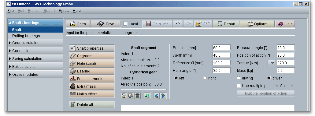
In order to create the cylindrical gear, select the first shaft segment. Click on the button ‘Force elements’ and select the menu item ‘Cylindrical gear’ from the submenu. Use the input mask to define the cylindrical gear. Enter the following input values:
| Position = 60 mm |
| Width \(b_{1}\) = 40 mm |
| Reference circle \(d_{T1}\) = 180 mm |
| Helix angle \(\beta _{1}\) = \(25^{\circ }\) |
| Pressure angle \(\alpha _{1}\) = \(20^{\circ }\) |
| Position of action = \(90^{\circ }\) |
| Torque \(T_{1}\) = 320 Nm |
| Mass \(m_{1}\) = 0.0 kg |
The first cylindrical gear is represented.
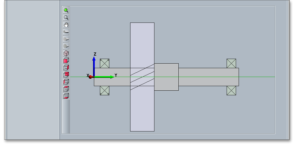
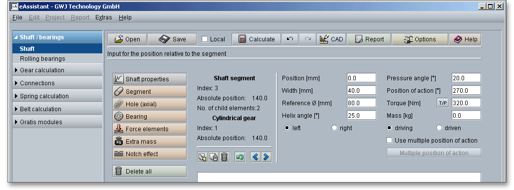
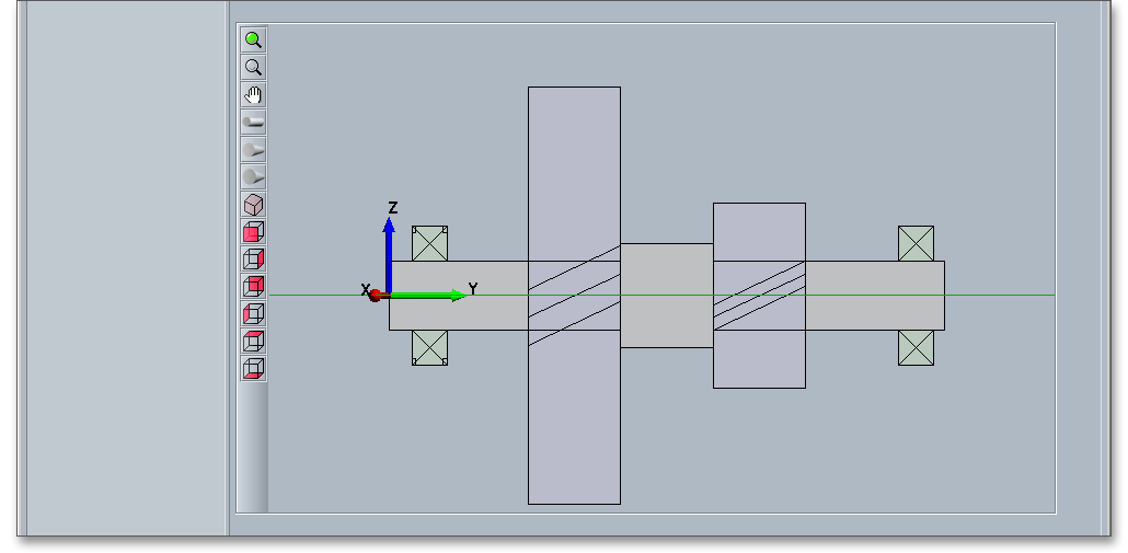
To create the second cylindrical gear, select the third shaft segment. Click on the button ‘Force elements’ and select the menu item ‘Cylindrical gear’ from the submenu. Please enter the following values into the input mask:
| Position = 0 mm |
| Width \(b_{2}\) = 40 mm |
| Reference circle \(d_{T2}\) = 80 mm |
| Helix angle \(\beta _{2}\) = \(25^{\circ }\) |
| Pressure angle \(\alpha _{2}\) = \(20^{\circ }\) |
| Power of action = \(270^{\circ }\) |
| Torque \(T_{2}\) = 320 Nm |
| Mass \(m_{2}\) = 0.0 kg |
Both cylindrical gears will be represented.
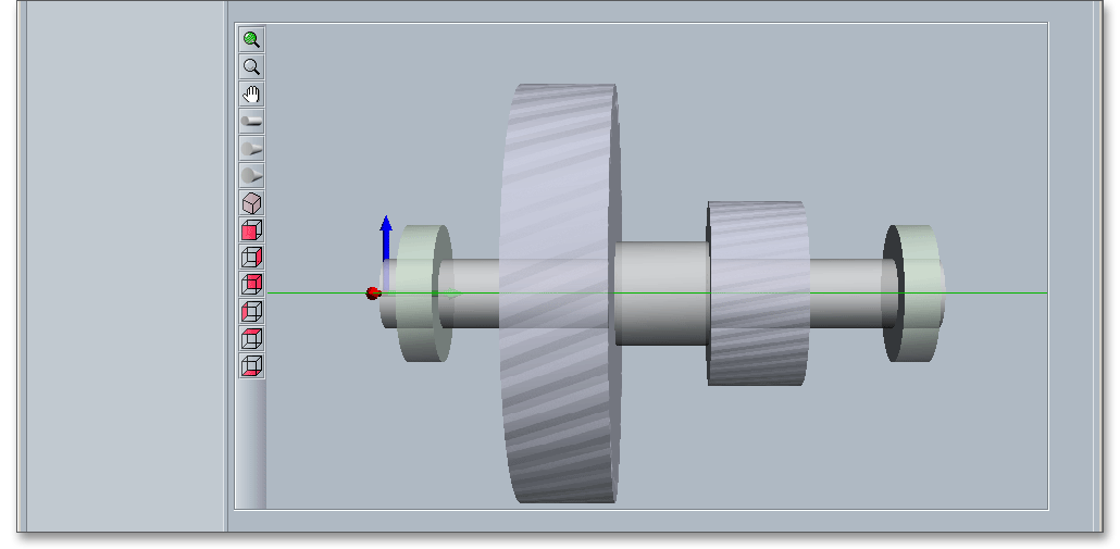
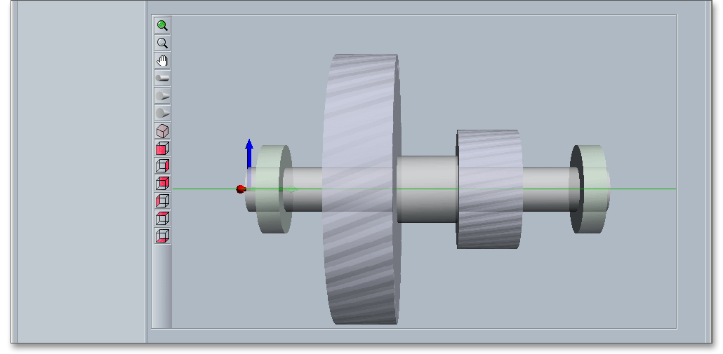
Then you can display the shaft in different views. Click the button ‘3D view’ and select the different views from
the toolbar and zoom into the graphic. Click on the button ‘Calculate’ and switch from the geometry part into the
calculation part. There you can run the calculations (find detail information in the section ‘How to start the
calculation’). The button ‘Report’ allows you to generate a report.
Clicking the ‘3D view’ button displays the three-dimensional presentation. The three-dimensional view allows to modify the elements. Select the element and change, for example, the position, length or diameter. To do so, please use the appropriate input fields. Click on the ‘2D / 3D view’ button again to switch back to the two-dimensional representation.
After defining the entire shaft geometry with the cylindrical gears and the bearings, you can start your calculation. To start the calculation, click the button ‘Calculate’. The button changes then its description into ‘Geometry’ and you get into the calculation part. The calculation part enables you to carry out the calculation. If you want to modify the geometry of the shaft, you have to go back to the geometry part. To do so, please click the button ‘Geometry’. With just one click, the following calculations can be carried out:
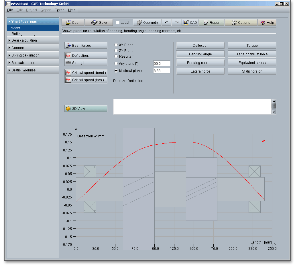
When you are in the calculation part of the module, it is not possible to change the geometry. In order to change the geometry, please go back to the geometry part by clicking the ‘Geometry’ button.
Now you can create the calculation report. Click on the button ‘Report’.

First the report configurator appears. The report configurator allows you to select which diagrams should appear in the calculation report and if the results of the strength calculation should be in the report, too. You can navigate through the report via the table of contents that provides links to the input values, results and figures. This calculation report contains all input data, the calculation method as well as all detailed results. The report is available in HTML and PDF format. The calculation report saved in HTML format, can be opened in a web browser or in Word for Windows. In HTML format, the figures are displayed in ‘gif’ format. In case a SVG viewer is available, you can display all graphics in SVG format. Right-clicking on the picture allows to zoom in and zoom out.
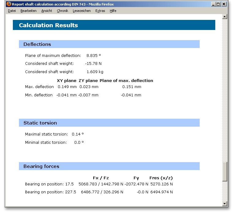
You may also print or save the calculation report:
When the calculation is finished, it is easy to save the calculation. You can save your calculation either to the eAssistant server or to your computer. Click on the button ‘Save’.

Before you can save the calculation to your computer, you need to activate the the option ‘Local’ in the calculation module. A standard Windows dialog for saving files will appear. Now you will be able to save the calculation to your computer.
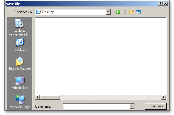
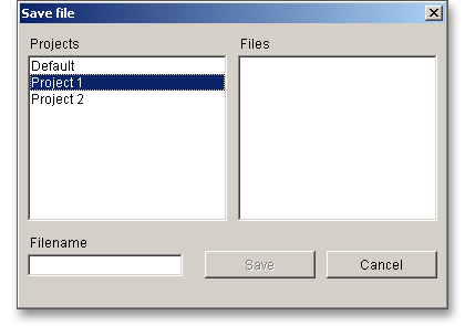
In case you do not activate the option in order to save your files locally, then a new window is opened and you can save the calculation to the eAssistant server. Please enter a name into the input field ‘Filename’ and click on the button ‘Save’.
Our manual is improved continually. Of course we are always interested in your opinion, so we would like to know what you think. We appreciate your feedback and we are looking for ideas, suggestions or criticism. If you have anything to say or if you have any questions, please let us know by phone +49 (0) 531 129 399-0 or email eAssistant@gwj.de.