

Features
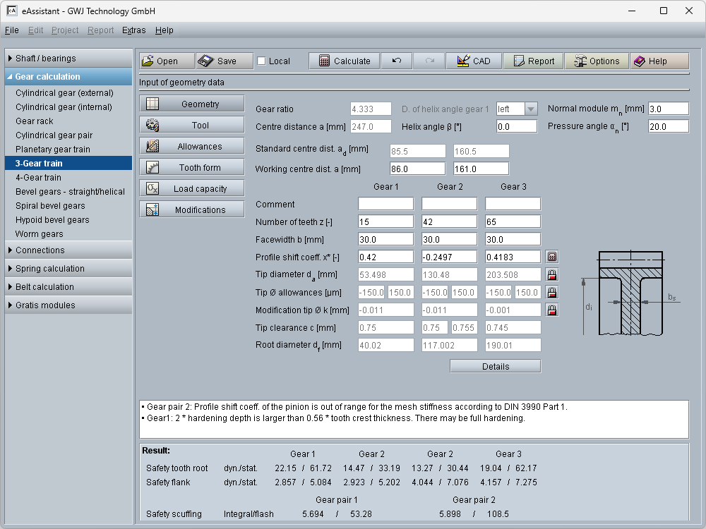
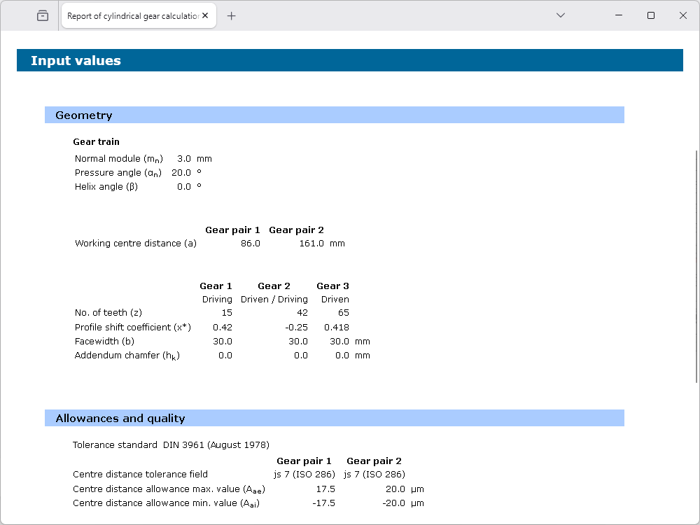
- Geometry of gear trains with 3 or 4 involute cylindrical gears according to DIN 3960, DIN 3961, DIN 3964, DIN 3967, DIN 3977 and DIN 868
- External spur and helical gears as gear train
- Input of pressure and helix angle in decimal degree or in degree, minute and second
- Alternative input for normal module as diametral and circular pitch
- Consideration of profile shift modification with optimization function for balanced specific sliding
- Extended range of possible profile shift modification (addendum modification)
- Specification of working centre distance or calculation of this from given profile shift coefficients
- Specification of a fixed working centre distance independently from the profile shift sum
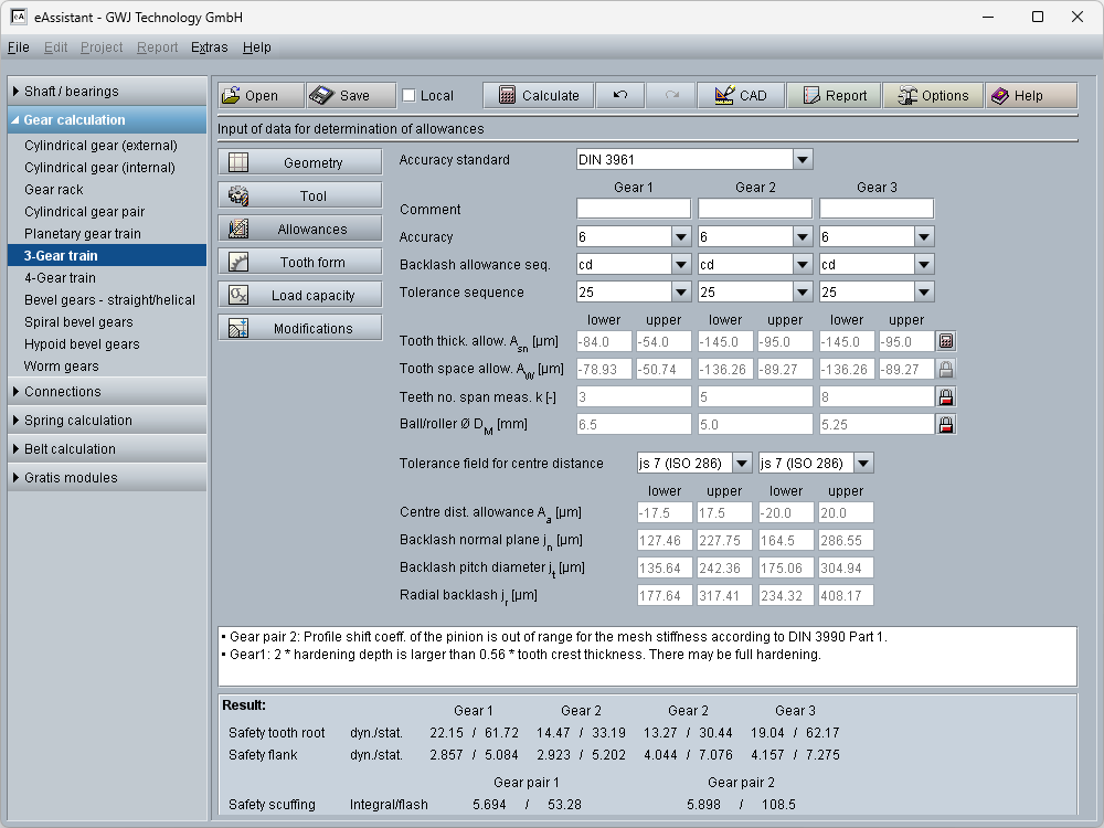
- Allowances for tooth thickness and centre distance can be selected from a database or can be defined individually
- Addendum chamfer/tip corner radius can be considered in the calculation
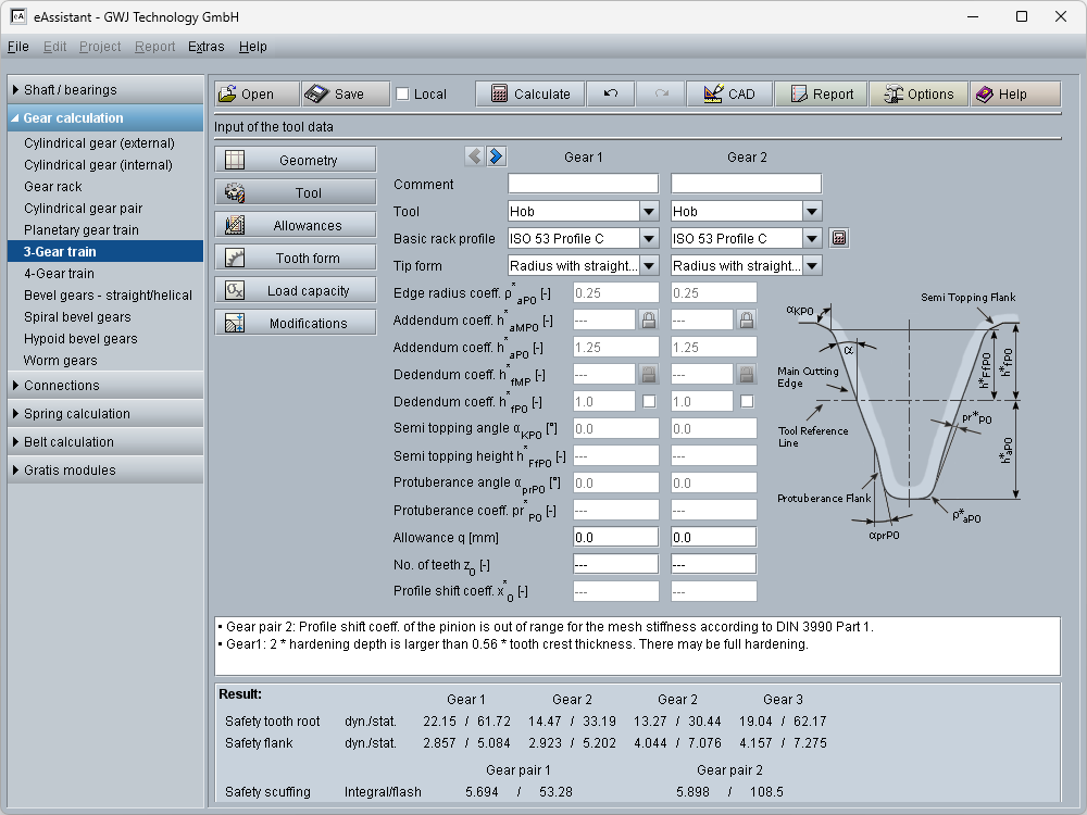
- Standardised basic rack tooth profiles for tools according to ISO 53, DIN 867 and DIN 3972 can be selected or individually definded, tools with shifted profile reference line, protuberance tools with or without allowance, dimensioning function for special basic rack tooth profiles, protuberance tools with shifted profile reference line, topping tools as well as tools with semi topping flank
- Full-depth teeth and stub tooth gears
- Type of tool: hob, gear shaper cutter and constructed involute
- Individual definition of the factor for the minimum tip tooth thickness
- Definition of the factor for the minimum gear ring thickness
- Calculation of the test dimensions and tooth thickness allowances based on measured values or given test dimensions
- Gear qualities/tolerances according to DIN 3961, DIN 58405, ISO 1328, ANSI/AGMA 2015 and DIN 3967 (1953)
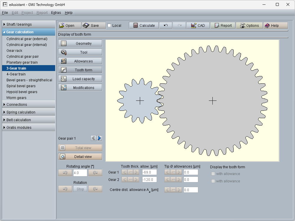
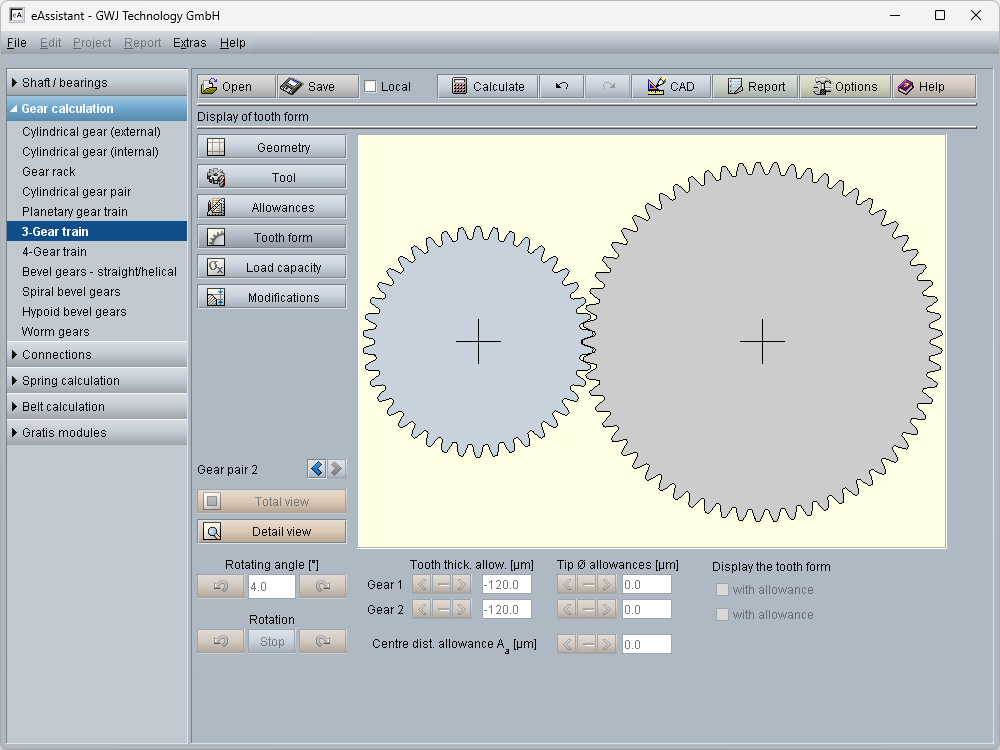
- Check for meshing interferences on the basis of the accurate tooth form with consideration of all tolerances
- Display of the accurate calculated tooth form with animation/simulation of the tooth mesh also for different tolerance fields
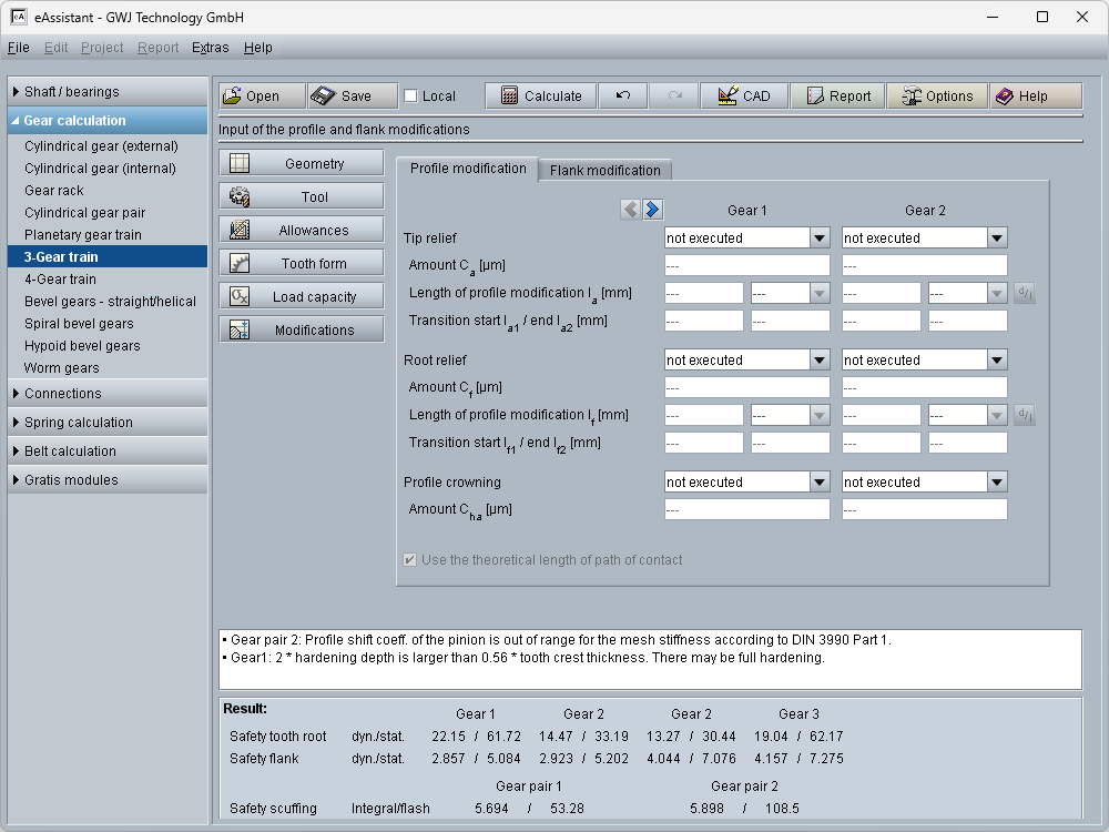
- Definition and consideration of profile modifications: linear and circular tip relief, linear and circular root relief, symmetric profile crowning
- Dimensioning of long or short profile relief, specification of the relief length or start diameter of the modification
- Definition of flank modifications: end relief, symmetric and asymmetric lead crowning including recommendations for amounts of the end relief or crowning according to reference values in DIN 3990
- Calculation with non-integer number of teeth, i.e., number of teeth with decimal places (available on request)
- Calculation with helix angle greater than 45 degree (available on request)
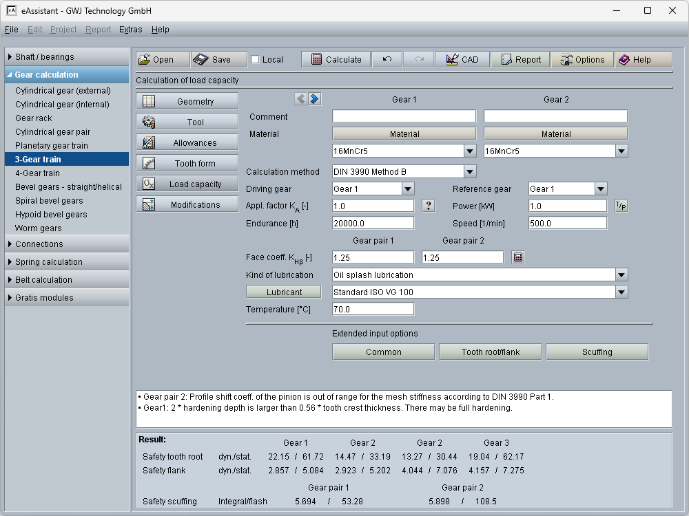
- Calculation of load capacity according to DIN 3990 method B, ISO 6336 method B and ISO/TR 13989 (scuffing) as well as ANSI/AGMA 2101-D04 (identical to ANSI/AGMA 2001-D04) with integrated material and lubricant database including ultra-clean steels with modified Woehler curves deviating from DIN/ISO
- Calculation of the load capacity for plastic materials according to VDI 2736
- Plastic materials available
- Maximum possible tooth normal force and maximum transmissible torque based on the required static and dynamic tooth root safeties
- Diagram of flash or contact temperature
- Consideration of grinding notches in the load capacity calculation
- Optimal hardening depth, manual input of hardening depth and consideration in the load capacity calculation
- Selection of mode of operation is possible for swelling, alternating or oscillating, individual input is also possible
- Consideration of rolling, shot peening, grinding or machining for the tooth root
- Calculation of the number of load changes or individual definition or specification of the number of tooth meshes
- Optional input of the carried width for the tooth root with different gear widths of gear 1, 2, 3 or 4 (DIN 3990/ISO 6336)
- Work hardening factor can be defined
- Life factors can be adapated (ISO 6336)
- Power loss by tooth friction, gearing efficiency according to Niemann
- Calculation of safeties for fatigue or limited life strength and static strength (tooth root, tooth flank/pitting, scuffing)
- Min./max. transverse contact ratio
- Unit switch between metric and U.S. customary unit system, unit switching function also for single parameters
- Adaption of decimal places
- Detailed calculation report in HTML and PDF format
- Output of CAD data via eAssistant CAD plugins or DXF interface
- GDE output (Gear Data Exchange) as XML file according to the VDI/VDE guideline 2610