Celler Straße 67 - 69
38114 Braunschweig
Germany
Fon: +49 (0) 531-129 399 0
Fax: +49 (0) 531-129 399 29
Mail: info@eassistant.eu
Web: http://www.gwj.de
Involute splines according to DIN 5480, DIN 5482, ISO 4156, ANSI B92.2M, ANSI B92.1
Features
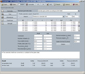
- Geometry of splined connections with involute splines according to DIN 5480, DIN 5482, ISO 4156, ANSI B92.2M, ANSI B92.1 and similar
- Geometry selection of profiles according to DIN 5480 including profile search function
- Geometry parameters can be defined individually
- Based on the selected profile, number of teeth, profile shift coefficients, normal module and pressure angle will be set automatically, tip circle and root diameter will be determined
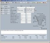
- Tool types: hob, gear shaper cutter and constructed involute
- Basic rack tooth profiles according to DIN 5480 for broaching, hobbing, shaping, cold rolling as well as for diameter centering can be selected or defined individually
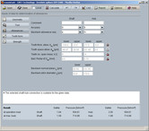
- Selection of gear accuracy and backlash allowance sequence according to mentioned standards
- Calculation of the tooth thickness allowances based on measured values or given test dimensions
- Calculation of the test dimensions
- Determination of backlash normal plane and backlash pitch diameter
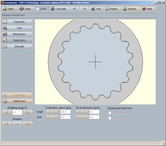
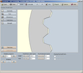
- Display of accurate gear tooth form
- Strength calculation according to Niemann, Winter, Hoehn
- Consideration of hub and load input and output geometry with load factor according to DIN 6892
- Dimensioning functions
- Consideration of load peaks and load direction changes
- Determination of permissible surface pressure from material properties
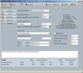
- Calculation of surface pressure and safeties for operation load and maximum load for shaft and hub
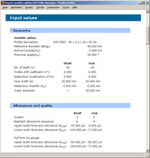
- Detailed calculation report in HTML and PDF format
- Output of CAD data via eAssistant CAD plugins or DXF interface
Description
The module allows a fast and easy calculation of the geometry and strength of involute splines according to DIN 5480 (03/2006), DIN 5482 (03/1973), ISO 4156 (10/2005), ANSI B92.2M-1980 (R1989) and ANSI B92.1-1996. The geometry can be selected conveniently from a data base. The profile search function can help the user to quickly identify a profile. An own input of involute spline geometry is also possible.
The following tool types are available: hob, gear shaper cutter and constructed involute. Basic rack tooth profiles can be selected according to DIN 5480 for broaching, hobbing, shaping, cold rolling and diameter centering. Tool standard rack tooth profiles for the other standards are also available, e.g., for ISO 4156 30° flat root or 30° fillet root. All parameters for the basic rack tooth profile can be defined individually or determined automatically.
In order to determine the tolerances, the gear accuracy and backlash allowance sequence according to DIN 5480, DIN 5482, ANSI B92.2 and ANSI B92.1 can be selected from listboxes. This will determine the permissible deviations and tooth thickness allowances. The calculation of the tooth thickness allowances can be done based on measured values or given test dimensions. Test dimensions, backlash normal plane and backlash pitch diameter are calculated as well. For the test dimensions, the required number of the teeth for span measurement and the diameter of ball or pin will be determined automatically by the program or can be entered by the user.
The display of the accurate tooth form is a special highlight. The 2D DXF output is possible, the eAssistant CAD plugins allow to generate 3D models for different CAD systems. The tooth thickness is considered as well, so that the tooth form could then be used for manufacturing (e.g., milling, laser cutting, eroding).
The strength calculation is based on Niemann´s „Maschinenelemente“ Vol. 1, Edition 2001. The permissible surface pressures are determined from material properties, so it is possible to use special materials. Materials can be selected from the data base. For a different load input and output, the load factor according to DIN 6892 will be calculated based on the defined geometry. In addition, load peaks and alternating torque can be specified for the calculation. Dimensioning functions for the operation nominal torque, the maximum load peak torque and the supporting length help the user. The calculation results for the surface pressure and safeties for operation load and maximum load for shaft and hub are determined and displayed immediately during the input of values.
After the calculation is finished, a calculation report can be generated. The report includes the calculation method, all important input values and detailed results. The calculation report is available in HTML and PDF format.

